- Home
- Product Categories
- Raspberry Pi HATs
- RELAYplate

RELAYplate
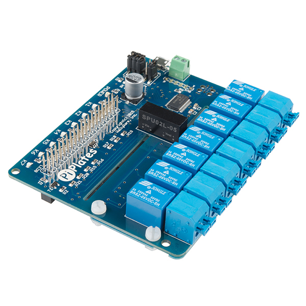
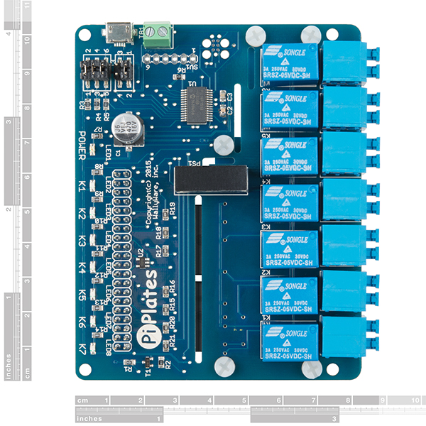
The RELAYplate from Pi-Plates is the first dedicated relay board for the Raspberry Pi designed to meet the safety requirements of UL 60950 while being capable of switching 120 volts AC. Each of the seven relays is UL rated to switch 1 amp at 120volts AC or 30 volts DC. And, like all Pi-Plates, you can stack these boards to increase your relay count to 56 using eight plates. The RELAYplate board is compatible with the DAQCplate and MOTORplate, allowing you to create the perfect stack of boards to control your project.
Pi-Plates are a family of stackable and interchangeable add-on circuit boards that allow you to interact with the outside world using your Raspberry Pi. Every Pi-Plate is designed to provide a robust set of features at minimal cost while using the fewest pins possible on the RPi header. Pi-Plates are mechanically and electrically compatible with all revisions of the Raspberry Pi with 40 pin headers (including the Pi 3 Model B and Pi Zero) and are designed to satisfy the needs of hobbyists, experimenters and professionals.
- Seven single-pole, single-throw relays
- Rated at 120 volts AC or 30 volts DC
- Currents up to 1 amp
- Convenient screwless terminal blocks
- Up to eight RELAYplates can be stacked together, providing 56 relays
- A single RELAYplate will run from the Raspberry Pi 5VDC supply
- Auxiliary power connectors provided for stacking multiple RELAYplates
- Includes programmable LED
- Seven LED annunciators provide visual relay status
- Designed to meet the stringent safety requirements of UL standard 60950
RELAYplate Product Help and Resources
Core Skill: DIY
Whether it's for assembling a kit, hacking an enclosure, or creating your own parts; the DIY skill is all about knowing how to use tools and the techniques associated with them.
Skill Level: Noob - Basic assembly is required. You may need to provide your own basic tools like a screwdriver, hammer or scissors. Power tools or custom parts are not required. Instructions will be included and easy to follow. Sewing may be required, but only with included patterns.
See all skill levels
Core Skill: Programming
If a board needs code or communicates somehow, you're going to need to know how to program or interface with it. The programming skill is all about communication and code.
Skill Level: Competent - The toolchain for programming is a bit more complex and will examples may not be explicitly provided for you. You will be required to have a fundamental knowledge of programming and be required to provide your own code. You may need to modify existing libraries or code to work with your specific hardware. Sensor and hardware interfaces will be SPI or I2C.
See all skill levels
Core Skill: Electrical Prototyping
If it requires power, you need to know how much, what all the pins do, and how to hook it up. You may need to reference datasheets, schematics, and know the ins and outs of electronics.
Skill Level: Rookie - You may be required to know a bit more about the component, such as orientation, or how to hook it up, in addition to power requirements. You will need to understand polarized components.
See all skill levels
Comments
Looking for answers to technical questions?
We welcome your comments and suggestions below. However, if you are looking for solutions to technical questions please see our Technical Assistance page.
Customer Reviews
2.7 out of 5
Based on 3 ratings:
1 of 1 found this helpful:
I built a wireless power sequencer.
EDIT: I lost a relay already which stuck on with a 0.30A load. The load was an LED lamp which perhaps had a large inrush current, but in any case I can no longer recommend this board. When I opened the metal enclosure there was the characteristic "burn out" smell and I assume the relay contacts arced as the other relays continued to work. I'd like to pull it apart and investigate, but at the price I need to return it intact.
EDIT #2: Definitely a sticking relay as it opens when lightly tapped. Will look at datasheet for the device just for grins. The relay is marked as 3A 250 VAC and the manufacturer says no more than 1 amp, so 0.30A shouldn't have been an issue.
I've finished reworking a used Furman RP-8 power conditioner to be a power sequencer for my virtual pipe organ's speakers. The RP-8 has plenty of empty space inside to house the RELAYplate and a Raspberry Pi 0w along with a 5v power supply. I can now control power to the remote speakers from any browser on a desktop PC or my smart phone. I can imagine a lot of other uses as well.
The documentation needs improvement and consolidation in one user manual, but the product works as advertised and was extremely simple to set up.
0 of 3 found this helpful:
No instructions!!
When I ordered this item I expected some type instruction to accompany it that would explain how to hook it up, but no such paperwork was included. So, I am unable to utilize it for the purpose intended.
Hello!
All the instructions and information on the board are provided in the documentation section above - you can find them by following these links: http://pi-plates.com/relayplate-users-guide/ http://pi-plates.com/examples/#Controlling_aRELAYplate_Remotely_with_Your_Web_Browser
Great relay board
Follow the documentation, download the python scripts and everything works
Nothing written is intended as professional design advise for the purpose of compliance with various national safety regulations, standards, or directives.
IEC/UL/EN60950-1 is obsolete, and should not be used for assessments of new products.
Does not meet construction and/or performance requirements per CSA/UL/EN62368-1 and/or 60950-1.
Could meet UL/EN61010-1 requirements where used per specific conditions of acceptability. But probably non sequitur, as the scope of this equipment is not intended for use in professional test and measurement equipment.
Not recommended for switching motor power where nameplate rating for FLA or FLC exceeds 50% of relay contact rating. Not recommended for DC current interrupt.
Creepage (spacing across a surface) requirements in mm, per IEC62368-1:
120V Basic = 2.4, 240V Basic = 4.0
120V Reinforced = 4.8, 240V reinforced = 8.0
[these requirements for material group III, pollution degree 3]
b. Your efforts to design a conforming product are commendable and very much appreciated. Compliance requirements are a morass and lie at the unholy intersection of law and physics. Few designers have successfully navigated a formal product submittal for stuff intended to be connected AC mains; most have to seek a member of the Dark Side of engineering (that would be me) to avoid being seduced by the power of hate and anger.
c. Am not at work, so clause number and wording from standards are based on my diminishing ability to remember the multitude of garbage in the hundreds of standards and directives that taught me to embrace my anger and hate and serve well to crush my being on a daily basis.
d. creepage requirements for 60950-1 are similar, as both are based on IEC60664-1. The seminal reference for the physics of electrical spacings is K. Stimper, ”The physical fundamentals of low-voltage insulation coordination”, VDE-Schriftenreihe, Vol. 57, Berlin, Offenbach vde-verlag 1991. Per 60950-1, a minimum clearance (spacing through air)is 1.0mm for 120V, but this number has no margin and is intended for a widget that is enclosed in a box. Spacings for safety are based on the mains transient voltage for the intended OV category. So the absolute minimum transient rating for 120V mains would be 800V, which is used to determine the increased spacing for 'Basic Insulation' and to ensure that the equipment can pass the di-electric withstand test ('hi-pot'). A more realistic transient voltage would be 1500V, which is the typical test level for Class I equipment per 60950-1.
e. Many are in denial on the impending cruel death of national standards based on IEC60950-1, so will ignore UL62368-1 and only reference product conformity per CSA/UL60950-1.
Would typically not recommend seeking a component recognition from UL, as there are other competent NRTLs that have more reasonable scheduling and rates.
Subclause 1.5 and annex P1 - ratings for PCB material per UL796.
subclause 3.2 and annex P1 - ratings for connectors per UL498.
subclause 3.3 and annex P1 - ratings for field-wiring connectors per UL486.
May the Light Side of The Force guide your future design efforts. And we all know that "once you start down the dark path, forever will it dominate your destiny". So there is no hope for me...
I have not bought it but it seems a good product, I do not understand why they complain that it does not come with instructions, it is a relay and its use is very simple // Yo no la he comprado pero parece un buen producto, no entiendo que se quejen por que no venga con instrucciones, es un rele y su uso es muy sencillo smart tv raspberry
Relays only rated for 1 amp @ 120VAC? That's a bummer. Given the option I'd take less, but larger, relays.
Not necessarily a problem - use the relays on the board to control a power relay.
To control DC current, use at least two relays in series. Paralleling relays is not good.
The relays are UL approved for 1 amp operation but they're labeled as being capable of operating at 2 amps. So we chose to be conservative in our specifications.
Anyone know of a similar board that supports us in 220/230V land? Otherwise this would be perfect for my application.
I see the relays are rated at 250vac, is there any reason Sparkfun why it can't be used on UK mains?
Because it's badly made, and probably doesn't have the required clearance and creepage distances.
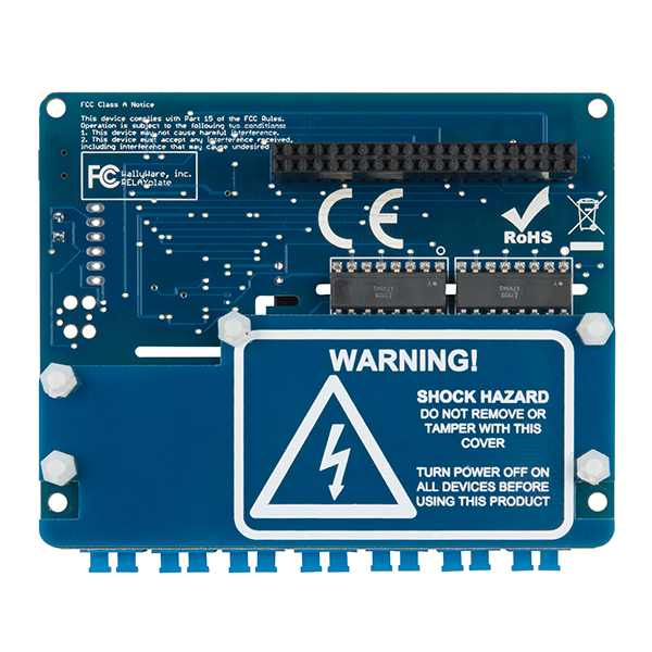
Evidently whoever designed this - not Sparkfun, incidentally - did not know that (decent...) relays implicitly provide rather good isolation, and thus decided to throw in a set of optocouplers and a isolated DC/DC supply. With proper design and component selection, you could've made this for $10-15 less while also allowing 250V AC.
The kicker? Sure, as designed it's isolated from the low-voltage side. But is the channel-to-channel isolation good enough? Probably not!
To be compliant with UL60950 you have to design for a single point failure. That's why there is an isolated supply and optocouplers - it doesn't matter what relay you use. If there is a breakdown between the contacts on a relay and the coil, the features I just described will prevent hazardous voltages from reaching your Raspberry Pi and everything attached to it.
The slot gap and trace spacing were all designed for 120VAC operation. Don't be fooled by some of those low cost relay boards from China - yes they may be less expensive but they will not protect you from a single point failure. And unless you put those things inside of a sealed box, they are inherently unsafe. For more on this see: http://pi-plates.com/the-problem-with-relays
Is that the optos on the rear of the board. Any idea what the slot gap should be for 240v