- Home
- Product Categories
- Raspberry Pi HATs
- SparkFun Servo pHAT for Raspberry Pi

SparkFun Servo pHAT for Raspberry Pi
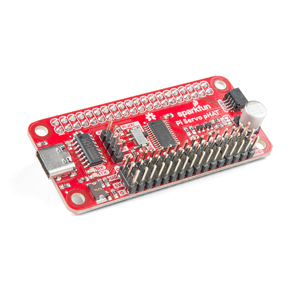
The SparkFun Servo pHAT for Raspberry Pi allows your Raspberry Pi to control up to 16 servo motors in a straightforward and uncomplicated manner via an I2C connection. Thanks to its I2C capabilities, this PWM HAT saves the Raspberry Pi's GPIO pins, allowing you to use them for other purposes. The Servo pHAT also adds a serial terminal connection, which will allow you to bring up a Raspberry Pi without having to hook it up to a monitor and keyboard. We have provided a Qwiic connector for easy interfacing with the I2C bus using the Qwiic system, and a 4-pin header specifically for connecting to the Sphero RVR.
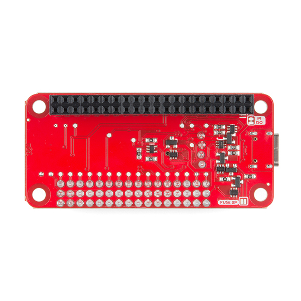
Power to the SparkFun Servo pHAT can be supplied through USB-C connector. This will power either the servo motors only, or power the servo motors as well as the Raspberry Pi that is connected to the HAT. We switched to USB-C to allow you to bring more current to your servos than ever before. This USB-C connector can also be used to hook up the Pi via serial port connection to avoid having to use a monitor and keyboard for setting up the Pi. To supply power only to the servo power rail (and not the Pi's 5V power rail), you just need to cut a small trace on the isolation jumper. Doing this allows you to drive heavier loads coming from multiple or larger servos. We've even added power protection circuits to the design, to avoid damage to power sources.
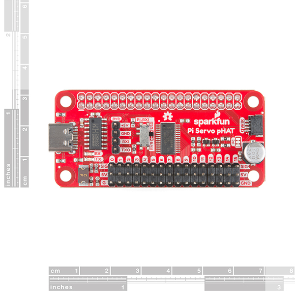
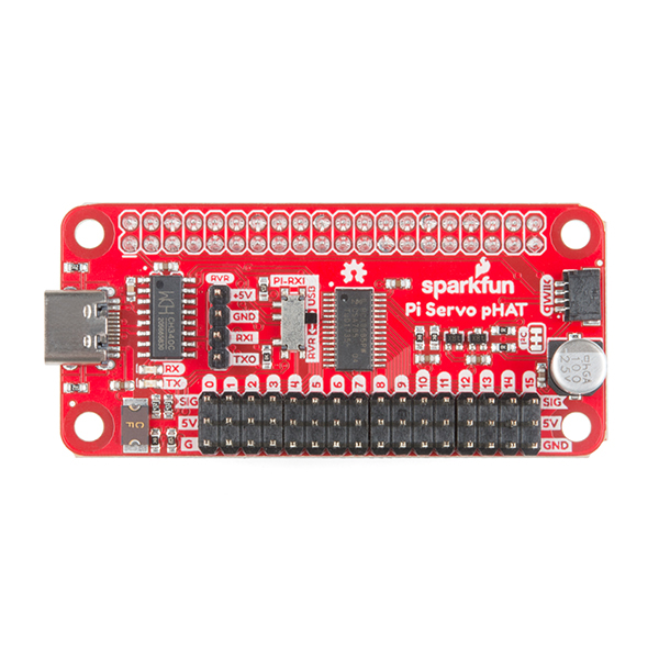
Each of this pHAT's 16 servo motor pin headers has been spaced out to the standard 3-pin servo pinout (ground, 5V, signal) to make it easier to attach your servo motors. The Servo pHAT is the same size and form factor as a Raspberry Pi Zero and Zero W, but it can also operate with a regular Raspberry Pi.
Note: This HAT includes headers to connect to a Raspberry Pi, so there is no soldering required to get up and running quickly.
- 16 PWM channels, controllable over I2C
- Qwiic connector
- 4-pin RVR header for connection to Sphero RVR
- USB-C connector
- 40-pin GPIO header for connection to Raspberry Pi
- CH340C USB Serial SOIC16
- Updated logic level conversion circuitry
- Power protection circuits
SparkFun Servo pHAT for Raspberry Pi Product Help and Resources
Setting Up the Pi Zero Wireless Pan-Tilt Camera
September 14, 2017
This tutorial will show you how to assemble, program, and access the Raspberry Pi Zero as a headless wireless pan-tilt camera.
Getting Started with the Autonomous Kit for the Sphero RVR
December 13, 2019
Want to get started in robotics? Look no further than the SparkFun autonomous kit for the Sphero RVR! Whether you purchased the Basic or Advanced kit, this tutorial will get you rolling...
How to Install CH340 Drivers
August 6, 2019
How to install CH340 drivers (if you need them) on Windows, Mac OS X, and Linux.
Basic Servo Control for Beginners
February 25, 2020
An introductory tutorial demonstrating several ways to use and interact with servo motors!
Pi Servo pHAT (v2) Hookup Guide
July 11, 2019
This hookup guide will get you started with connecting and using the Pi Servo pHAT on a Raspberry Pi.
Core Skill: Robotics
This skill concerns mechanical and robotics knowledge. You may need to know how mechanical parts interact, how motors work, or how to use motor drivers and controllers.
Skill Level: Competent - You may need an understanding of servo motors and how to drive them. Additionally, you may need some fundamental understanding of motor controllers.
See all skill levels
Core Skill: Programming
If a board needs code or communicates somehow, you're going to need to know how to program or interface with it. The programming skill is all about communication and code.
Skill Level: Competent - The toolchain for programming is a bit more complex and will examples may not be explicitly provided for you. You will be required to have a fundamental knowledge of programming and be required to provide your own code. You may need to modify existing libraries or code to work with your specific hardware. Sensor and hardware interfaces will be SPI or I2C.
See all skill levels
Core Skill: Electrical Prototyping
If it requires power, you need to know how much, what all the pins do, and how to hook it up. You may need to reference datasheets, schematics, and know the ins and outs of electronics.
Skill Level: Rookie - You may be required to know a bit more about the component, such as orientation, or how to hook it up, in addition to power requirements. You will need to understand polarized components.
See all skill levels
Comments
Looking for answers to technical questions?
We welcome your comments and suggestions below. However, if you are looking for solutions to technical questions please see our Technical Assistance page.
Customer Reviews
4.8 out of 5
Based on 5 ratings:
1 of 1 found this helpful:
Not so fast bucky - Updated
About a week after posting this review I was contacted by the design engineer. He suggested I try a different base frequency and provided a link to a test program with the new frequency. Which I did - Problem solved. Thank you ...
I tested this unit using a standard Futaba servo motor connected to the first position, and a Raspberry Pi Zero. As soon as the Pi was booted the servo began to buzz and became warm. The supplied test programs operated the servo however the supplied timing constants only accounted for about 45 degrees on either side of center and had to be doubled to get a full 90 degrees. The buzzing continued the entire time the servo was connected and the servo became too hot to touch after about ten minutes of testing.
Modification needed
Quoting the datasheet "To conserve power, no internal pull-up resistors are incorporated on the hardware selectable address pins and they must be pulled HIGH or LOW." The schematic shows the pins unconnected. I soldered a wire across pins 1 to 5 and connected it to pins 24 and 25. 25 is grounded so all the address pins are now grounded giving an address of 0x40. Once I did this, it all worked as expected.
Really nice upgrade over the previous version
I had the previous version running a servo on an automatic dog door. Unfortunately, the motor was near the limit for the board and would brown-out the Pi Zero occasionally. The USB-C is a really nice upgrade!
From a novice's perspective, this is very easy to use
This was surprisingly very easy to use for someone with absolutely no prior experience with Raspberry Pi and very little experience in coding. It did almost everything I wanted it to do, but I didn't realize the limitations of a HAT in that you lose ALL of the GPIO pins which doesn't work for the specific application I had in mind which requires buttons to control the servos. I have since moved on and am connecting servos directly to the GPIO pins and using the jittery software PWM, but this is still a great little device.
Read twice - program once, or three times... (I'm new here)
Utilizing the documents tab on the product page, you'll be greeted with the red links of confusion. I went straight to the "hookup guide" and read it over a few times to make sure I wasn't missing anything before physically assembling the device to the Pi and servos. The USB-C connector; it is BOTH a serial-UART and a separate power input. I bought this primarily to provide high power input to a gang of servos, the high power capability of USB-C is just what was needed. (Note to who wrote the tutorial section, please change the X's to checkmarks? or green icons? for the power control table.)
Make sure you have the RPi OS on the TF card before you start. I was running something weird and I got lost at this point as to why it wasn't running at all.
The sudo pip3 commands worked as listed in the guide. (Author; for beginners, can the tutorial be edited to separate things better? PyPi install kinda blended in too well with the "local installation" and caused me some issues in terminal.) Newbies like me- where it says Python Package Operation... use Thonny in your rasbian and build this into a new file (like Arduino IDE, but not). For low-power RPi, learn how to initiate your .py program in terminal to save computing resources. The GUI desktop and Thonny running the program will make an automation stutter badly.
Ensure your raspi-config interfaces are all activated or you'll get I/O problems, my connections were good, software enabled I2C... not so much. (OSError: Remote I/O error) Checking the I2C connection section (Author... maybe update? was it just me?) sudo apt-get install i2ctools did NOT work... sudo apt-get install -y i2c-tools = did work. Needed the hyphen between the c-t.
Overall: This device is solid, inexpensive and, after some trial and error, working beautifully. Now to write some python programs to use a PS4 controller to move the robot arm project I printed.
Is there a way to use a higher voltage supply (6V-7.4V) for the servos? I assume you'd need to cut the isolation jumper and find a supply point to solder on to.
Hi Gumercules, Yes, you are correct. If you solder directly to the "SERVO" net (aka any one of the 5V header pins on the servo connections, aka the "middle pin"), then you can supply a higher voltage). If you don't need all 16 channels, then you could use one of them as the "input". But you could also solder to the bottom of the header. Note, there are some ideal diode circuits to keep this isolated from the rest of the board. This means that if you go this route, then you do not need to cut the PI ISO jumper.
You could also inject up to 6V on the RVR "5+" pin, but keep in mind that this will also power the PCA9865 with your injected new voltage, and that IC has a absolute maximum supply voltage of 6V (recommended "normal max" of 5.5V). Also note, that with this option, you'd also want to make sure to cut the PI ISO jumper.
Please be careful when attempting either of these options, because you can risk damaging your pi. I'd definitely recommend viewing the eagle files thoroughly and double-checking all your connections before powering it up and/or plugging it into your Pi.
Good luck and thanks for reaching out!
I just fried a RPI 4B doing this. I looked at the schematic and saw the reverse current protection, so it seemed safe to provide 8.4V to the servo rail, through one of the servo connectors. The RPI was powered through a 5V supply (20W) and then a 8.4V supply was connected to the ground and middle pin of the servo #15 connector. The RPI red LED very very faintly turned on. I removed everything immediately. Removed the servo pHAT, but the RPI never came back alive (tried different supplies and cables). Fortunately I had another RPI laying around, so I was back up and running quickly on 5V. Then after everything was verified to work again, I cut the 5V servo trace on the back of the servo pHAT, and tried again using the same 8.4V supply, and this is working like a charm.
So maybe my board had an issue, but it's also possible that the protection on the board is not working as expected. Hopefully this is helpful.
Also, on your Qwiic_Py documentation page, you definitely have a typo:
"The qwiic Python package current supports the following platforms:"
Should be "... currently ...."
Edit: Do you guys need an editor? I'm pretty good at editing. See how much practice I get at it? :-)
I think you meant to post this comment on this blog. Thanks for the heads up on the typo, I'll pass the information along.
Hello Sirs, can I use this header, and use the ribbon connection to your GPIO breadboard T connector? At the same time?
I need to get 18 servos running (hexapod). Is it possible to run two of these on a single Raspberry Pi 4? Thanks!
Any chance of getting one of these with right angle servo headers and broken out address pins so that you can have multiple chained together?
I think we might be making a Qwiic version (with less channels???), but we will probably break out the address pins on that. I know that for this release, it was pretty tough just to squeeze all the components; especially with the RX switch and RVR, servo, and GPIO headers covering most of the real estate.
Unfortunately, we don't offer custom board manufacturing. Maybe a 3x20 pin right angle M/F header might be worth scouring the internet?
Totally understandable, the layout looks great considering how much stuff is packed on there! I just wasn't sure if you were going to offer a header-less version like you do with other dev boards. I'll definitely keep an eye out for the Qwiic version. It's just unfortunate that these chips only offer 16 channels when a hexapod usually requires 18. Thanks!
You can configure the sub-addresses (see datasheet). Although that is not the design intention for those addresses, but it should allow you to control up to (3) chips (unfortunately, we don't have step-by-step instructions for that). I am pretty sure 16 is the maximum channels offered, but if you find a better IC, let us know.
In this case, the hat was designed to be used with the Sphero RVR kit, so we have everything preassembled.
Hey, sounds great!! I like the idea of being able to power stronger motors.
However, I think you've got the wrong datasheet linked. The PCA9685 (according to your current link) is a: 16-channel, 12-bit PWM Fm+ I2C-bus LED controller
We're not talking about LED controllers here. Or we're not supposed to be! :-)
So tell you what, if you'll fix the link, I'll delete this comment. (I.e., if I can.)
Thanks, Leland...
Edit: Also, fix the document link, and I'll buy one right away!! Maybe two, if you fix it quickly enough! :-)
Edit 2: Or is it actually the same controller?? (And I was wrong above?) Maybe that's possible, given my current knowledge level. (Pun intended.) :-P
You are correct, the PCA9685 was originally designed for LED PWM control. However, servos (this doesn't control DC motors) are controlled with PWM signals. Since the PCA9685 is capable of producing the proper PWM signals, it can be used to control the servos. (*I think I calculated the PWM resolution to equate to less than half a degree on a 90° servo; based on the datasheet.)
It's the same controller. It can be used as a generic PWM driver so it'll work for servos as well as LEDs.
Will this be able to control the Bolt without the need for the RVR at some point? What language is used to program the RVR using the pHat interface?