- Home
- Product Categories
- Addressable
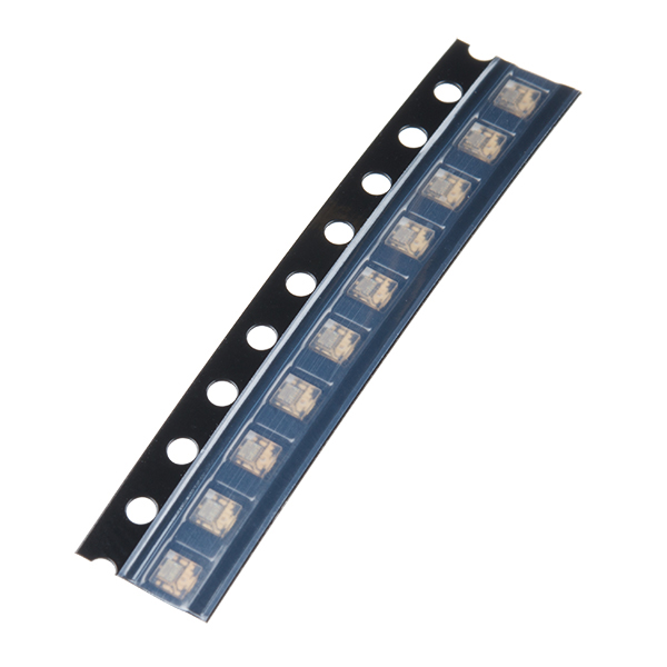
- SMD LED - RGB APA102-2020 (Pack of 10)

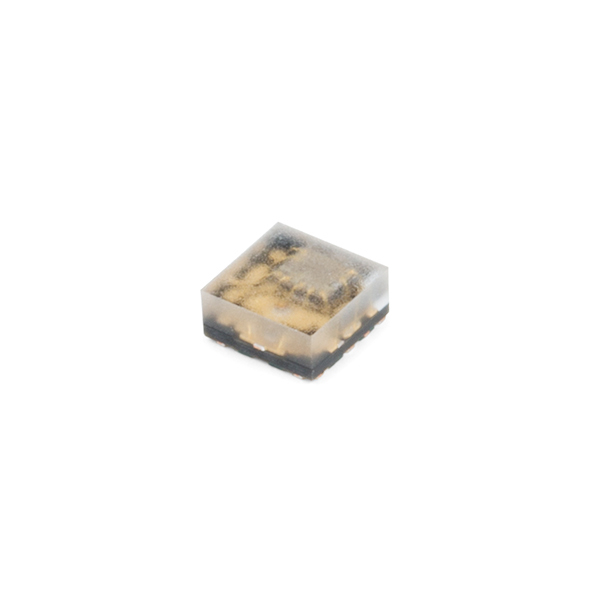
This version of the APA102 (or “DotStar”) is an astoundingly tiny, 8-pin, 2020-sized (2x2mm) SMD LED. With an integrated control circuit embedded, the APA102-2020 is incredibly bright and colorful. If you look really closely, you can see the tiny gold chip hidden in there, along with minuscule gold wires connecting the chip to the LED. This miniaturized version of the APA102C LEDs found in our Lumenati line is perfect for applications needing a bit of color while not possessing a lot of real estate.
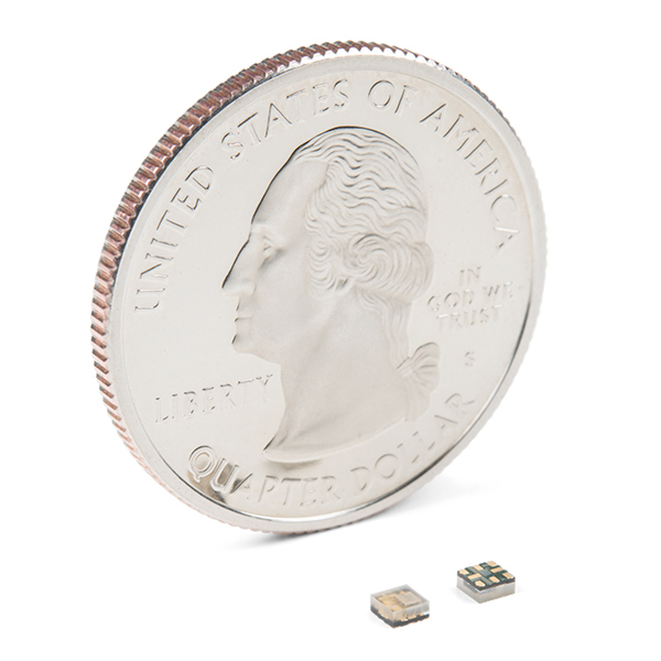
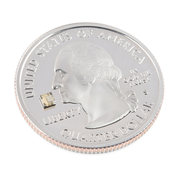
Each APA102-2020 in this strip of 10 contains three even smaller LEDs, hence RGB (Red/Green/Blue). It is important to remember just how small these LEDs are. They can be extremely difficult to solder, so we do recommend that you have good SMD soldering skills before incorporating the APA102-2020. But, hey, that's why we give you these in strips of 10!
- Red: (619--626nm) @ 300--330mcd
- Green: (520--535nm) @ 420--460mcd
- Blue: (465--467nm) @ 160--180mcd
- 8-pin design
SMD LED - RGB APA102-2020 (Pack of 10) Product Help and Resources
LumiDrive Hookup Guide
January 17, 2019
The LumiDrive LED Driver is SparkFun’s foray into all things Python on micro-controllers. With the SparkFun LumiDrive you will be able to control and personalize a whole strand of APA102s directly from the board itself.
Core Skill: Soldering
This skill defines how difficult the soldering is on a particular product. It might be a couple simple solder joints, or require special reflow tools.
Skill Level: Competent - You will encounter surface mount components and basic SMD soldering techniques are required.
See all skill levels
Core Skill: Programming
If a board needs code or communicates somehow, you're going to need to know how to program or interface with it. The programming skill is all about communication and code.
Skill Level: Rookie - You will need a better fundamental understand of what code is, and how it works. You will be using beginner-level software and development tools like Arduino. You will be dealing directly with code, but numerous examples and libraries are available. Sensors or shields will communicate with serial or TTL.
See all skill levels
Core Skill: Electrical Prototyping
If it requires power, you need to know how much, what all the pins do, and how to hook it up. You may need to reference datasheets, schematics, and know the ins and outs of electronics.
Skill Level: Competent - You will be required to reference a datasheet or schematic to know how to use a component. Your knowledge of a datasheet will only require basic features like power requirements, pinouts, or communications type. Also, you may need a power supply that?s greater than 12V or more than 1A worth of current.
See all skill levels
Comments
Looking for answers to technical questions?
We welcome your comments and suggestions below. However, if you are looking for solutions to technical questions please see our Technical Assistance page.
Customer Reviews
No reviews yet.
All, There are two different versions of this device - the APA102 2020-256-8 and the APA102 2020-256-6 and this is causing confusion. The footprint on this board has 6 pins but the data sheet linked shows 8 pins. Since the two extra pins are Vcc and GND which are redundant with the 6 pin layout, it may not matter. However, I am a believer in following the datasheet and I created a EAGLE footprint for the 8-pin version that matches the datasheet on this page.
Beware! The pictures of the devices above match the pictures in the datasheet I pulled from Sparkfun in Aug 2018. The datasheet has since changed, and the pinout (and internal die and bond layout) is DIFFERENT. Power and ground pins are now called out as middle pins instead of end pins.
This new scheme works very nicely if you lay the chips sideways, and run power and ground traces down the middle of all the chips in a row, stubbing out to make connections to the middle pins are you go. And the input and output signals are adjacent, and out of the way of the power and ground runs. Using 4 layer boards with power and ground planes would be even better. Bit more expensive, but better connections with fewer weird issues (had startup glitch issues with a decent 2 layer board, even with lots of low ESR capacitance). YMMV.
Is there an Eagle CAD foot print for this?
Apparently not. I'm looking for a KiCad footprint, but Eagle would work too. The CAD drawing in the datasheet is terrible and the dimensions don't add up. Also, the pictures show that there are 2 additional pads down the center. On the datasheets I see for this part on Chinese sites, they indicate that these pads should be connected to VCC and GND. Has anyone successfully used these and do you know if the two pads must be connected, or can be ignored?