- Home
- Product Categories
- Arduino Boards
- SparkFun RedBoard Turbo - SAMD21 Development Board

SparkFun RedBoard Turbo - SAMD21 Development Board
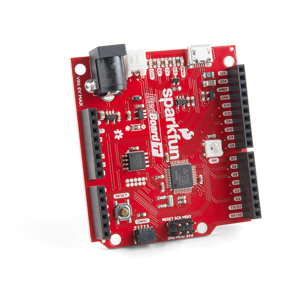
If you’re ready to step up your Arduino game from older 8-bit/16MHz microcontrollers, the SparkFun RedBoard Turbo is a formidable alternative. At its heart, the RedBoard Turbo uses the ATSAMD21G18, which is an ARM Cortex M0+, 32-bit microcontroller that can run at up to 48MHz. With an impressive 4MB of external flash memory and a UF2 (USB Flashing Format) bootloader, the RedBoard Turbo provides you with an economical and easy to use development platform if you're needing more power than the classic RedBoard.
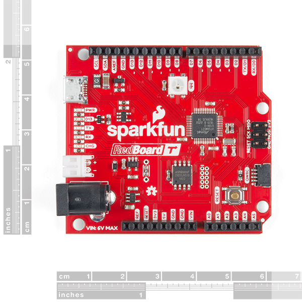
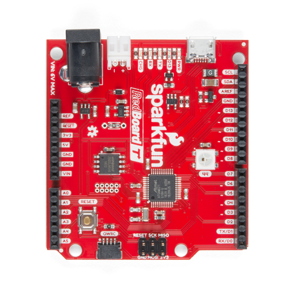
The SparkFun RedBoard Turbo has been equipped with a USB interface for programming and power, a Qwiic connector, an RTC crystal, WS2812-based addressable RGB LED, 600mA 3.3V regulator, and a variety of other components. To power the RedBoard Turbo, just plug it into a USB port on your computer via the micro-B port or directly into the wall with the 5V tolerant barrel jack. Not near a USB port? No problem, the SparkFun RedBoard Turbo is also equipped with a LiPo Battery connector (for a single-cell 3.7-4.2V litium-polymer battery). The MCP73831's charge current is configured by a resistor value between 66kΩ and 2kΩ, to charge the battery at a rate between 15mA and 500mA, respectively. By default, the board is configured to charge the battery at around 250mA. If you’ve used any Arduino before, this pinout shouldn’t surprise you – the layout meets the Arduino 1.0 footprint standard, including a separate SPI header and additional I2C header.
The RedBoard Turbo can even be flashed over the Mass Storage Class (MSC) just like a removable flash drive, thanks the the UF2 bootloader. With this bootloader, the RedBoard Turbo shows up on your computer as a USB storage device without having to install drivers! From the Arduino IDE, you’ll still need to select the correct port on your machine, but you can just as easily use another programming language such as CircuitPython or MakeCode.
Note: The barrel jack connection on the RedBoard Turbo has a lower input voltage than most Arduino development boards. Make sure that you are using a power supply below 6V. Please be aware that the RedBoard Turbo is also a 3.3V device and not a 5V one like the original RedBoard.
- ATSAMD21G18 32-bit/48MHz ARM Cortex-M0+
- 4MB Flash Memory
- 32KB SRAM
- 32KB of EEPROM (emulated in Flash)
- 26 GPIO Count
- 14 ADC Channels at 12-bit Resolution
- Analog-to-Digital and Digital-to-Analog Converters (ADC & DAC)
- Vin: 4.2V-6.0V for charger - otherwise 3.5V-6.0V
- VBATT: 3.7V Lipo
- VCC: 600mA @3.3V
- Arduino R3 Layout
- Integrated USB Controller
- RGB LED
- UF2 Bootloader
- Qwiic Connector
SparkFun RedBoard Turbo - SAMD21 Development Board Product Help and Resources
RedBoard Turbo Hookup Guide
January 24, 2019
An introduction to the RedBoard Turbo. Level up your Arduino-skills with the powerful SAMD21 ARM Cortex M0+ processor!
The ClockClock Project
October 8, 2020
Tell the time with this fantastic Alchitry project using clocks to make a clock!
Keyboard Shortcut, Qwiic Keypad
April 25, 2019
A simple project using the Qwiic Keypad and the RedBoard Turbo to create your own custom hotkey-pad.
GPS Geo-Mapping at the Push of a Button
September 27, 2019
Let's ramp up our GPS tracking skills with KML files and Google Earth. We'll make a tracker that logs location and allows us to visualize our steps with Google Earth.
Qwiic Pro Kit Project Guide
November 7, 2019
The Qwiic Pro Kit was designed to allow users to get started with Arduino without the need for soldering or a breadboard. We've included three inputs (a joystick, accelerometer, and proximity sensor) and one display that can be daisy chained to the RedBoard Turbo (SAMD21) Development Board.
Adding More SERCOM Ports for SAMD Boards
February 4, 2019
How to setup extra SPI, UART, and I2C serial ports on a SAMD-based boards.
Core Skill: Programming
If a board needs code or communicates somehow, you're going to need to know how to program or interface with it. The programming skill is all about communication and code.
Skill Level: Rookie - You will need a better fundamental understand of what code is, and how it works. You will be using beginner-level software and development tools like Arduino. You will be dealing directly with code, but numerous examples and libraries are available. Sensors or shields will communicate with serial or TTL.
See all skill levels
Core Skill: Electrical Prototyping
If it requires power, you need to know how much, what all the pins do, and how to hook it up. You may need to reference datasheets, schematics, and know the ins and outs of electronics.
Skill Level: Rookie - You may be required to know a bit more about the component, such as orientation, or how to hook it up, in addition to power requirements. You will need to understand polarized components.
See all skill levels
Comments
Looking for answers to technical questions?
We welcome your comments and suggestions below. However, if you are looking for solutions to technical questions please see our Technical Assistance page.
Customer Reviews
3.8 out of 5
Based on 8 ratings:
2 of 2 found this helpful:
Nice Board. Arduino Library issue.
Just starting to use the board. I'm working on a problem with connecting a shifting uSD breakout board. After updating an SD library example sketch for the Serial port name change, I found that the standard SD library has some Serial.print statement embedded. A couple src/utilities/~.cpp files have these Serial.print statements embedded. This could get complicated if other libraries do the same. Otherwise the board is performing as advertised. The hookup guide is quite accurate and complete and excellent for getting up and going.
Battery Connector+++
What's not to like!? UNO form factor with Qwiic and a LiPo battery connector. Now if i could figure out a way to dis-able the comm LEDs with something other than a chisel... It would be nice, for boards with battery power, to have a jumper that disables the LED. Just my thoughts on that. I like the SAMD21, as they seem to compile faster than, for example, the ESP8266. So i can make mistakes way faster with this board. Haven't used the Python yet. It's very easy to find when setting up the Arduino application. The board pops up on the list of ports in the Arduino application with the correct name for easy identification. The SerialUSB issue is similar, i think to the other SAMD21 boards i have. Definitely a win for me!
Edit 2020-07-28
Taking one star as it does not work reliably with the OpenLog. This is a known issue - check the forums for progress,
Nice Board
It’s a nice board and works well. Make sure you read the page the board is on for some important info about setup. It’s not plug ‘n play but very easy to setup for the Arduino IDE. Also serial is different. You have to change it for it to work. All on the info page for the board.
Neat little board
As a novice tinkerer, this board is fun to use. I'm excited to learn how to program it to do the things I want. As of now, I have only used the pre written examples. They were written for the non-turbo board, but with a few Serial word replacements(check the forum for specifics "red board turbo") I was up and blinking. Quality looks good, and I am happy with the purchase.
Nice board, fast, a little flaky
I'm pretty impressed with this so far in most aspects, except one. Uploading sketches is pretty much a crapshoot. Sometimes works, sometimes not, tried it on three different computers, without hub. Usually uploads work, but sometimes it takes 10 to 20 tries.. I'm totally LOVING the Qwiic interface, using the small OLED display and the twist has been far easier than I would have thought. I'd actually like to see a version without the arduino headers, and maybe multiple Qwiic ports.
Hardware OK, lack of software support
I've tried so many microcontrollers, including AVR and Arduino variants and shields, this board offered so many options with the mememory, speed and ports...I tried the blinking led with no problem whatsoever, BUT once I tried the serial communications and I coouldnt compile it! So I tried the serial communication example and the same issue, so I research the problem but I found that others havehad the same issue from the start and no answer has been given. It's not a hardware or installation issue, lack of suppor to solve this.
Serial works a bit differently on this board than it does on others. Please see the serial example in the hookup guide for more information.
If you still have questions, you can contact support on this page.
Nice Board and good quality
An impressive board. I have two of them right now, and I prefer to use this board than a standard Arduino UNO or Nano. Without the complicated wiring, connecting sensors is made simple by the Qwiic interface/connection. If you have made the decision to definitely incorporate your board and sensors into your project, it is simple, uncomplicated, and uncluttered. Regarding memory, this board provides a wide range of possibilities. Pls. remember to change Serial in the Arduino IDE to SerialUSB when writing new sketches or when editing existing ones. In addition to the board itself, I appreciate the Sparkfun quality and customer service. Unfortunately, one portion of the order was incorrectly sent and shipped without any problems right away.
JTAG not Supported by ARDUINO IDE, QWIIC was inconsistent
So when I bought this board I was expecting the JTAG connector to work with the Arduino IDE imagine my surprise when it said not supported, I had it working with other software. Tried using the Qwiic connectors it seem to work with some boards and not others I used a sparkfun 128x32 OLED and 64x64 Oled did a address scan of both the boards and they showed up, but wouldn't work when I use the example code for the boards. I moved it to the Arduino standard pins with jumpers still wouldn't work so basically both were DOA. So I plugged in a competing board it worked fine on the standard SCL SDA Arduino pins with 3.3 and 5.0 volts but not the Qwiic using the Sparkfun demo code it would not address scan on the qwiic.
A 32-bit ARM Arduino-like board, with built-in battery management and bonus flash storage, for (slightly) under $25? And from a non-shady vendor like SparkFun who supports their stuff? Very, very cool.
Nice board especially the price. I suspect a lot of folks may start to use it instead of the UNO. A word to the wise if you plug in your favorite UNO shield that is populated with an ISP header, Shields such as the proto shield DEV-1382/13819 and the microSD shield dev-12761, the 3.3volts will be shunted to the 5.0v USB supply.There are several ways around this but if you don't wish to cut board traces you can pull the 5.0v pin from the shield's ISP stackable header. As a side note the ISP header connections are not documented on the schematic for this board. This is also the case for the case for the SAMD21 Dev Breakout (DEV-13672 ). This information is available on the graphical data sheet and the eagle files.
Is it possible to power this board using an external regulated 3.3V power supply? I am worried I could damage the board by connecting a external 3.3V directly to the 3V3 pin header. Thanks and best regards!
Providing an external 3.3V power will not damage the board.
Hi guys, so... I may have (I did) hooked up an LCD powered by the 5V USB power on the board and then hooked up the logic lines directly.. to the 3.3V board. Dang it. So now the charge LED flickers slightly for a few seconds when powered on and the board is not recognized. As someone who has been in this game for a while, that was a dumb mistake. My question is: anyway to fix this besides replacing the SAMD21 IC? Any help would be much appreciated, thank you. At least the good news is that they are in stock! :)
I got it back!!! I held down the reset button and quickly pressed it a few times (in desperation) and maybe crossed some other wires with tears, but I saw the blue LED flash! Then the board came up on my Mac and I am back in business! I'll probably should order a second board for a backup, this is a great dev board!
Hi there, it sounds like you were looking for technical assistance. In the future, you can use the link in the banner above, to get started with posting a topic in our forums. Our technical support team will do their best to assist you.
That being said, you probably reset the board into the bootloader. It is a good way to try to recover your board if something funky happened. If you can't get to the bootloader... your last resort would be to re-flash the board.
The graphical data sheet URL should also be listed under Documents. I had to go to the hookup guide to find the link buried in there.
It has been added/linked to be more convenient for users.
Some random things I have noticed when using this board:
On a Mac, make sure you are using a quality USB cable, or you will have difficulty getting the USB port to show up in the Arduino IDE. At least that has been my experience. This is not unique to this board with Macs.
If you are connecting this to a Pixy2, you will have to modify the Pixy2 library and replace references to the "Serial" object with "SerialUSB". I had to modify Pixy2.h, Pixy2CCC.h and TPixy2.h in this way. I also had to remove the ZumoBuzzer.cpp from the library in order to compile my sketch. I don't have a Zumo robot, so I didn't bother debugging the issue.
After modifying many libraries and pulling my hair out I found a quick solution, start your sketch with "#Define Serial SerialUSB" (before all the other library calls) to map the SerialUSB to Serial - then any standard AVR arduino libraries will work with the turbo without modification. I've written code that will work on either board flavor by just commenting or uncommenting that snippet.
Does the new board allow the user to turn off that insanely bright power LED? (Yes I know I can put tape over it, but it's still using power). Other than that, I love my original Redboard.
There is a cuttable trace for the power LED.
But, if the schematic is to be believed, we're back to 330Ω resistors on the LEDs. The other current RedBoards have transitioned to 4.7kΩ, much easier on the eyes (and batteries!)
I see a debugging socket on the board (unpopulated). What is the pitch of the socket? What debugger does that require? Also, if I load my own code through the debugging socket, does that invalidate the UF2 bootloader, or can it still be used?
Thanks.
Those pins are for SWD; they are 50 (not 15... see reply below) mil pitch. In production, we use an Atmel-ICE programmer. You can use any similar product as long as it is AVR/SAMD compatible. As with all programmers, you are flashing the microcontroller... so yes, the bootloader would get overwritten. However, the bootloader is available in the Firmware folder of the GitHub repository if you need.
Thanks for the reply. One further thing -- do you use Atmel Studio for development, or something else (I'm a PIC developer used to MPLAB X; I'm not sure that covers SAMD parts)? Thanks again.
Unfortunately, I don't know. The SAMD21 is an Atmel chip, so you should be able to do your own development with Atmel Studio.
I thought those were 50 mil pitch?
(Also, note for non-US folks, a mil is 0.001 inches.)
You are correct. According to the Eagle files, they are 50 mil pitch (.05"); I heard my coworker wrong.