- Home
- Product Categories
- Monochrome
- SparkFun Transparent Graphical OLED Breakout (Qwiic)

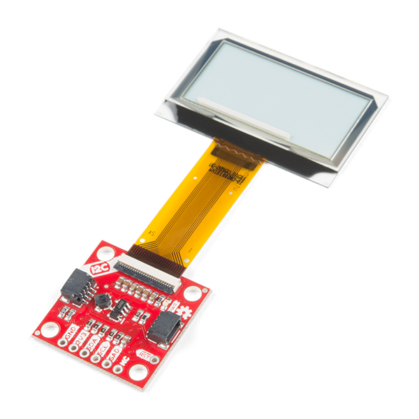
SparkFun Transparent Graphical OLED Breakout (Qwiic)
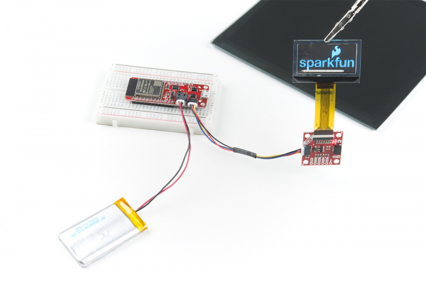
The future is here! The SparkFun Qwiic Transparent Graphical OLED Breakout allows you to display custom images on a transparent screen using either SPI or I2C connections. Brilliantly lit in the dark and still visible by daylight, this OLED sports a display area of 128x64 pixels, 128x56 of which are completely transparent. Utilizing our handy Qwiic system, no soldering is required to connect it to the rest of your system making it easy to get started with your own images. However, we still have broken out 0.1"-spaced pins in case you prefer to use a breadboard.
The Arduino sketch required to drive this display requires quite a bit of dynamic memory, meaning that it is not going to fit on a smaller controller like an ATmega328. Control of the OLED is based on our new HyperDisplay library and any controller with larger RAM should have no problem. In addition, your 3.3V source should be robust enough to supply around 400mA to the display.
Note: The I2C address of the Graphical OLED is 0x3C and is jumper selectable to 0x3D. A multiplexer/Mux is required to communicate to multiple Graphical OLED sensors on a single bus. If you need to use more than one Graphical OLED sensor consider using the Qwiic Mux Breakout.
The SparkFun Qwiic Connect System is an ecosystem of I2C sensors, actuators, shields and cables that make prototyping faster and less prone to error. All Qwiic-enabled boards use a common 1mm pitch, 4-pin JST connector. This reduces the amount of required PCB space, and polarized connections mean you can’t hook it up wrong.
- 128x56 transparent pixels (128x64 total pixels)
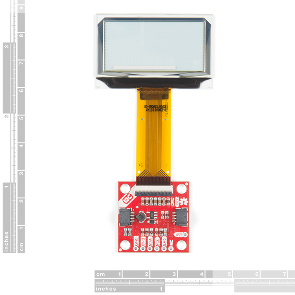
- Display area 35.5 x 18mm
- Glass area 42mm x 27.16mm
- 1-bit color depth
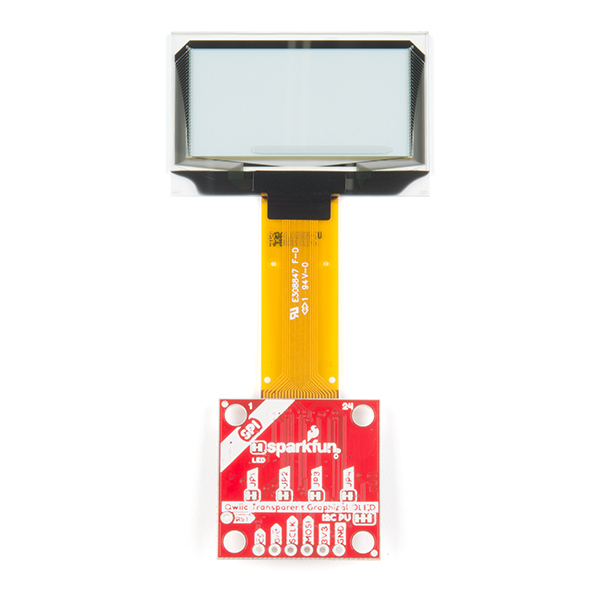
- I2C or SPI operation
- 400 kHz I2C, 10 MHz SPI
- I2C Addresses: 0x3C (Default), 0x3D
- Qwiic compatible and standard PCB footprint
- Operates and communicates at 3.3V
- Less than 200 mA current draw pixels all-on
SparkFun Transparent Graphical OLED Breakout (Qwiic) Product Help and Resources
Transparent Graphical OLED Breakout Hookup Guide
March 7, 2019
The future is here! Our Qwiic Transparent Graphical OLED Breakout allows you to display custom images on a transparent screen using either I2C or SPI connections.
Everything You Should Know About HyperDisplay
February 20, 2019
This is a tutorial to go in-depth about the SparkFun HyperDisplay Arduino Library.
Core Skill: Programming
If a board needs code or communicates somehow, you're going to need to know how to program or interface with it. The programming skill is all about communication and code.
Skill Level: Competent - The toolchain for programming is a bit more complex and will examples may not be explicitly provided for you. You will be required to have a fundamental knowledge of programming and be required to provide your own code. You may need to modify existing libraries or code to work with your specific hardware. Sensor and hardware interfaces will be SPI or I2C.
See all skill levels
Core Skill: Electrical Prototyping
If it requires power, you need to know how much, what all the pins do, and how to hook it up. You may need to reference datasheets, schematics, and know the ins and outs of electronics.
Skill Level: Rookie - You may be required to know a bit more about the component, such as orientation, or how to hook it up, in addition to power requirements. You will need to understand polarized components.
See all skill levels
Comments
Looking for answers to technical questions?
We welcome your comments and suggestions below. However, if you are looking for solutions to technical questions please see our Technical Assistance page.
Customer Reviews
4.6 out of 5
Based on 5 ratings:
3 of 3 found this helpful:
Display is Good - Sparkfun Drivers not flexible
Hello, I bought this display under the impression that although it is graphical, the Display driver would support writing (drawing) text. However, that is not the case.
customer support said "The display is matrix rather than a character display"
I know, but matrix displays can draw text with a capable driver...)
I found this driver: https://github.com/olikraus/u8g2 That is capable of writing beautiful text on the display!
Open the "Helloworld" example:
Uncomment the following: U8X8_SSD1306_128X64_NONAME_HW_I2C u8x8(/* reset=*/ U8X8_PIN_NONE);
Support 8 lines on the display.
Then write to Position (x) and Line (Y) using the command: u8x8.drawString(0,0,"hELLOW WORLD);
Just what I wanted!
Good! display
I use it. https://www.denshi.club/cookbook/arduino/mkrzero/mkr-zero-8-oled.html
That's really cool, thanks for sharing your project!
Very cool works with sdd1306 library
I'm using this display to make a heads up display, and I have to say it works prefect using the thing plus and the hook up guide. I did have issues getting the text to flip so it would display near the bottom by the ribbon cable. After contacting customer service they responded quickly and suggested I contact the author of the font program. So after searching the web for days I decided to try the adafruit ssd1306 library and it worked. then I used ssd1306 asci library and it had display rotation i2c and spi examples and it was exactly what I needed. I have to say the hook up guides are fantastic with links to datasheets and eagle files Thank you Sparkfun for taking the time to support your products. Well done. I will be buying more of theses displays and the wonderful thing plus. If you don't know about the thing plus yet check it out it is amazing.
i guess it is good but very fragile
had to bye a new one because the wire got cut.
I bought this from one of SFE's retail partners. Works great with Adafruit's MicroPython display library using their MCP2221A board. My plans for it on a RPi under Python will thus be a breeze to develop.
The board also looks epic at night.
I did discover that at the time of this comment (8 Sep 2020) that the features lists the wrong I2C addresses, it should be 0x3C (default) and 0x3D with jumper, the current documentation lists 0x30/0x31, which are a bit low, this proved to be a 'gotcha' for about... a minute until I noticed what was up.
Sorry about that and thanks for pointing that out. It has been fixed.
Awesome, thanks!
Hi there, would anyone have a basic circuit diagram (just pin to pin would be fine) for connecting the SparkFun Transparent Graphical OLED Breakout (LCD-15173) SPI to a SparkFun ESP32 Thing - not the Plus (DEV-13907) using the "HyperDisplay Library", "HyperDisplay SSD1309", "HyperDisplay Transparent Graphical OLED" with the settings...
Option 2 (SPI): Connect SCLK and MOSI to the SPI port of your choice (13 and 11 for SPI on Uno-like boards) Also connect D/C and CS to two unused GPIO pins of your choice (and set the proper pin definitions below) Don't forget power - connect 3.3V and GND
define USE_SPI 1 // Choose your interface. 0 = I2C, 1 = SPI
I could swap to a ESP32 Thing Plus and follow the hookup guide is thats a better way. Many thanks Jon
SPI pins on the ESP32 can technically be multiplexed to anywhere, though they are fastest on their default pins. https://docs.espressif.com/projects/esp-idf/en/latest/esp32/api-reference/peripherals/spi_master.html
If I remember correctly I use pins 18, 19, and 23 for clock, miso, and mosi. You should verify that the default SPI object in Arduino does indeed use these pins. There are ways to override the pin selection in Arduino if you need.
Would this work on Arduino Nano? If so, what are the schematics? Would the code still be the same?
Hi there, it sounds like you are looking for technical assistance. Please use the link in the banner above or the steps in the troubleshooting section, to get started with posting a topic in our forums.Our technical support team will do their best to assist you.
That being said, the schematic for this board can be found under the Documents tab (underneath the product pricing, it can be easy to miss with the white-on-white tabs). Additionally, the hookup guide for this display is also linked under that tab. It will have all the hardware assembly and code examples to get you started with using the display with our ESP32 Thing Plus. Unfortunately, as mentioned in the hookup guide, the code to get this display running does require a lot of RAM. Therefore, I don't think the Arduino Nano will work with the display.
Can you post the datasheet for the TOLED itself? Would be very helpful. Thank you. ACTUALLY SCRATCH THAT-- looks like it was in the Github. Thanks!
Oops! We're posting it on the Documents tab anyway b/c that's where it oughtta go! Thanks for calling that to our attention. P.s. even though it says confidential we have gotten permission to share it with you all.
Is it possible to replace the flat cable? I have a project I've been working on for a while, trying to find a transparent OLED display, but I need the flat cable to go from the display at a 90 degree angle, and be a little longer.
Good question - glad you asked! It would be very challenging to remove the cable from the glass of the display, but it is really easy to replace the display module thanks to the FPC connector on the PCB. I'm wondering if you might still be able to use this display though, because the cable is very flexible. There is a short (~1mm) stiffener protruding from the glass but after that the cable can bend more than 90 degress with a pretty small (less than 1mm) radius. I will say if you choose an extreme bend in the cable that it is best not to bend it back and forth too many times. I hope that can help!