- Home
- Product Categories
- Power Accessories
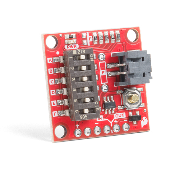
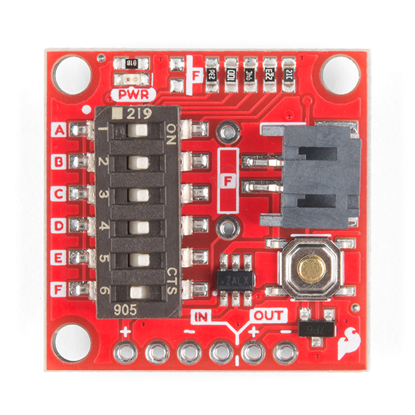
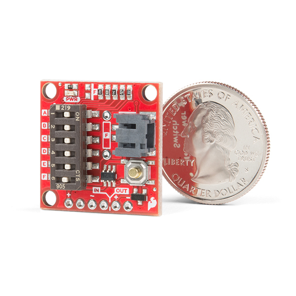
- SparkFun Nano Power Timer - TPL5110

SparkFun Nano Power Timer - TPL5110
Sometimes we want our projects on, but sometimes we want to turn them off for a while to save power. The SparkFun Nano Power Timer will run while only consuming minimal power (approximately 35nA) and turn your project on after a set amount of time. When you are done polling your sensors, posting data to the web, writing to your logger, or planning world domination, your microcontroller can tell the Nano Power Timer to turn off the power. No more running your microcontroller all day when you only want to read the ambient temperature once per hour.
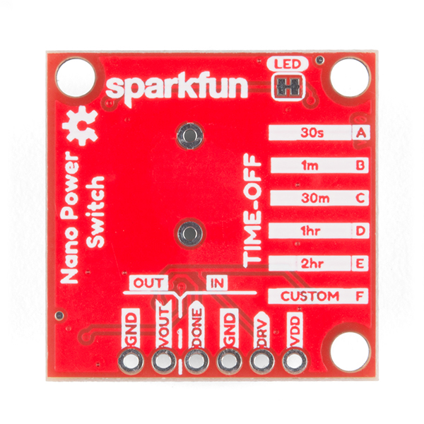
The TPL5110 delay is configured with the use of resistors. We've added a six-way DIP switch to select one of the five preinstalled resistors. The sixth switch is attached to a pad to add your own PTH (or SMD) resistor. The delays associated with the preinstalled headers are shown on the bottom of the board for quick setup. Additionally, you can select more than one switch to combine the resistors in parallel (up to 26 options not including the custom resistor), check out the hookup guide for a nice chart as to the total resistance and corresponding delay for each combination.
The Nano Power Timer can handle voltages between 1.8V and 5.5V as well as current up to 1.1A with times from 100ms to two hours (preconfigured settings range from 30s to 2h). You will find a button on the board which will allow you a quick override to the delay so you can turn your project on whenever you like.
- Supply Voltage: 1.8V to 5.5V
- Current consumption at 2.5V: 35nA Typical (50nA Max)
- Selectable Time intervals: 100ms to 7200s (2 hours)
- Timer Accuracy: 1%
SparkFun Nano Power Timer - TPL5110 Product Help and Resources
TPL5110 Nano Power Timer Hookup Guide
June 6, 2019
The TPL5110 Nano Power Timer is ideal for applications that require low power, and especially those projects that are running off of a LiPo battery. The Nano Power Timer will turn on your project after the set amount of time, continuously.
Core Skill: Soldering
This skill defines how difficult the soldering is on a particular product. It might be a couple simple solder joints, or require special reflow tools.
Skill Level: Noob - Some basic soldering is required, but it is limited to a just a few pins, basic through-hole soldering, and couple (if any) polarized components. A basic soldering iron is all you should need.
See all skill levels
Core Skill: Programming
If a board needs code or communicates somehow, you're going to need to know how to program or interface with it. The programming skill is all about communication and code.
Skill Level: Noob - Programming will be limited to basic drag and drop interfaces like ModKit or Scratch. You won't be writing code, but you will still need to understand some basics of interfacing with hardware. If you?re just using a sensor, it's output is analog.
See all skill levels
Core Skill: Electrical Prototyping
If it requires power, you need to know how much, what all the pins do, and how to hook it up. You may need to reference datasheets, schematics, and know the ins and outs of electronics.
Skill Level: Competent - You will be required to reference a datasheet or schematic to know how to use a component. Your knowledge of a datasheet will only require basic features like power requirements, pinouts, or communications type. Also, you may need a power supply that?s greater than 12V or more than 1A worth of current.
See all skill levels
Comments
Looking for answers to technical questions?
We welcome your comments and suggestions below. However, if you are looking for solutions to technical questions please see our Technical Assistance page.
Customer Reviews
4 out of 5
Based on 2 ratings:
Usefull for datalogging
Very easy to use and very efficient to save power for my datalogging needs. Be very carefull with the use of other power source in the same time of the timer, I burned one piece because of that (USB).
.
.
Before implementing a hardware solution, Arduino users might want to investigate if the Low Power library will meet their needs. It works on the Uno (328p), Zero (SAMD21), and other variants.
https://learn.sparkfun.com/tutorials/reducing-arduino-power-consumption/all
Nice =D
Can you please put a 10k pulldown to avoid floating signal in the DONE pin? Mosfet request seems a good idea as well
I believe the current design follows the example layout in the datasheet, where the
DONEpin should be connected to the microcontroller's GPIO. Unfortunately, I am unsure what you mean by a MOSFET request.That being said, a good way to have a record of your request/suggestion on the next revision, would be to file an issue in the GitHub repository.
I would be interested in a similar device that, rather than waking on a timer, wakes up whenever the input voltage exceeds a certain threshold. It would ideally sleep after the input voltage goes below a certain, lower threshold (or at the input of a microconroller).
the perfect solution for my project ... Almost! Was going to order several, now none.
please provide datasheet of the on-board mosfet . schematic indicates that the mosfet on board is spec'd at 1.1Amax /../600mOhm .
I'm assuming the 600mOhm is the Rds-ON which is much too high for my application. maybe that's a mis-print?
My project is a low power, sleeps most of the time, wakes once per hour to take a data sample and transmit. However, during transmit, my board peaks >2A @ Vbat. If Rds is 600mOhm the voltage drop thru this board will be 1.2V which will put the voltage to the application board lower than brown-out. (also, there's likely additional diode voltage drop thru the mosfet which will make the application voltage even lower!)
Idea for next-gen version of this product: pair the TPL5110 nano-power timer with a more useful MOSFET, perhaps a N-mosfet that has very-low Rds-ON, or higher current capability P-channel?. I can see more applications if this product could switch more power.
According to the MOSFET part markings, 7P6, it looks like it is from Diodes Inc. Part Datasheet ZXMP6A13F.PDF
The TPL5110 supports P-Channel MOSFETs for high-side switching only. There are P-MOSFETs that have much lower Rds-on ratings and can support higher currents.
I can't believe you guys didn't leave pin 6 broken out, so you could use it in One-shot mode!
One-shot mode is very useful for interactive battery powered projects. In this mode, it will remain in low power off condition, until a button press to wake it up, and then power back off when either the timer runs out or if it gets a Done signal sooner.
You need to make a new version of the board with the One-shot pin broken out.
WARNING! WARNING! WARNING!
Do the following at your own risk. You can make the board unusable!!!!!!!!! I am not responsible for damage to your board.!!!!! A very fine tip on your soldering iron is required. In retrospect I should have used my hot-air rework station.
I just did some VERY delicate surgery on pin 6. Pin 6 is connected to VDD on a trace that runs from pin 1, under the chip to Pin 6 and then to to the switch. due to the trace under the chip you must lift pin 6. This is very delicate , pin 6 is fragile!!!!!!!!!!!! Using a verrry fine tip on my Hakko I was able to lift pin 6 from the board. I then connected pin 6 with some wire wrap wire to a the center pin of a 3 pin header. On pin of the header goes to VDD and the other goes to ground. That way I can use a shorting plug to switch modes. When connected to GND, one shot mode works great!!!!
On my second attempt on another board I managed to break off pin 6. When pin 6 is not connected operation is undetermined.
However when looking at the chip, I noticed that I could see the broken end of pin 6's lead frame in the hole. (Part of the chip package broke off).
I inserted a piece of fine wire to touch the end of the exposed lead frame. I then used Supper Glue to hold the wire to the lead frame. There was no where to solder it. After this it worked OK.
I got Lucky
I have posted Instructions with picture on my Site: Firestone Robot Foundry
It may be possible to use conductive paint to fix the broken pin. ????
Conductive paint doesn't last very long, so probably not a good option.
I agree. I am preparing some picture sof what I did along with instructions.Will post later today.
Isnt that the DRV pin, which is broken out?
And I think it will wait on forever for the DONE signal. If you need an turnoff timeout, it would be on your controller.
As for one-shot mode where the on mode never fires except for a button press, I didnt see it defined how it works if none of the resistor dip switches are enabled. That might cause the timer to be disabled, essentially a one-shot only mode? Would have to try it.
The EN/ONE-SHOT pin is different from the DRV pin.
"When EN/ONE_SHOT = HIGH, the TPL5110 works as a TIMER. When EN/ONE_SHOT = LOW, the TPL5110 turns on the MOSFET one time for the programmed time interval. The next power on of the MOSFET is enabled by the manual power ON."
So this EN/ONE-SHOT pin is tied to VDD on this board. This forces the TPL5110 to permanently operate in Timer mode.
In Timer mode it will periodically interrupt (power-cycle) the DRV pin at set intervals regardless of the DONE pin. All the DONE pin does is turn it off sooner. So if you tie the DONE pin to GND (disabling it), it will stay ON and then periodically turn off for 50 ms at the set interval and continually repeat.
In ONE-SHOT mode it will remain off (forever) until the DELAY/M_DRV pin it toggled to VDD. Then remain ON for the set interval or until the DONE signal if it is received sooner than the set interval, and then remain off again.
An example of ONE-SHOT mode is when you have a toy and you want it to remain off, saving power, and then only activate when you press a button. Then after it does it's thing, go back to power off.
I appreciate the feedback and I'll certainly keep that in mind for the next revision. We discussed the most useful function of the board which we felt was using it for remote or Internet of Things applications. We felt that what you're describing could be solved with a simple switch. Is there a use case where the one-shot function would be more useful then a switch?
The One-Shot mode is more than just a switch. With a switch you will need to manually turn it on/off. Or with a momentary switch you will need to have external components for a flip-flop and timers or something to have it somewhat automated to turn off after a period. This TPL5110 chip is all in one, with very low power standby.
One-Shot mode is very useful for external triggering of an event. Instead of periodically waking up in Timer mode and checking for some event if it occurred or not, thus wasting some power usage just for checking. Like for example a door switch, can wake it up and send an IOT message out, then go right back to low power shutdown state.
Also to note the TPL5110 is better than just low power sleep modes of microcontrollers. It can power-off all your circuitry like power regulators or other components that have higher standby currents. So for battery powered projects nothing else (yet) comes close to this savings.
A fair point, I'll make sure to make a note for the next revision.