- Home
- Product Categories
- Weather
- SparkFun MicroMod Weather Carrier Board

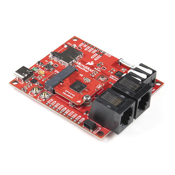
SparkFun MicroMod Weather Carrier Board
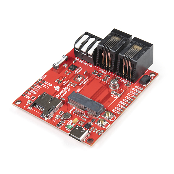
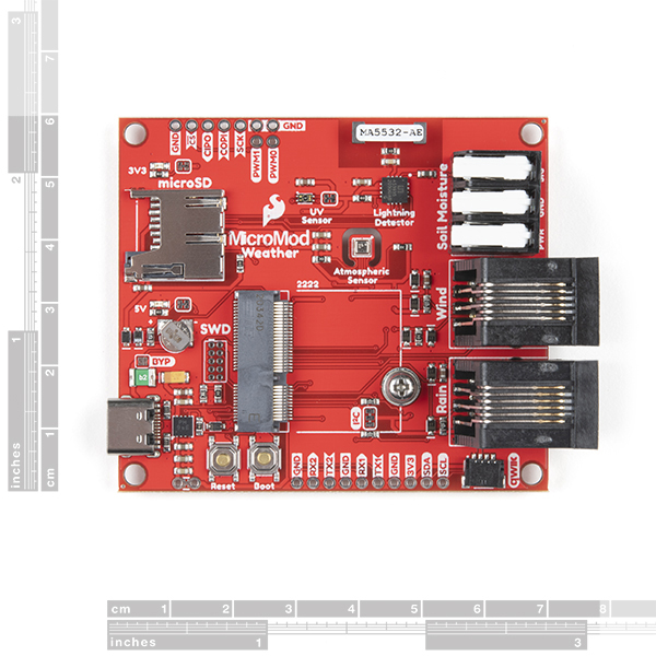
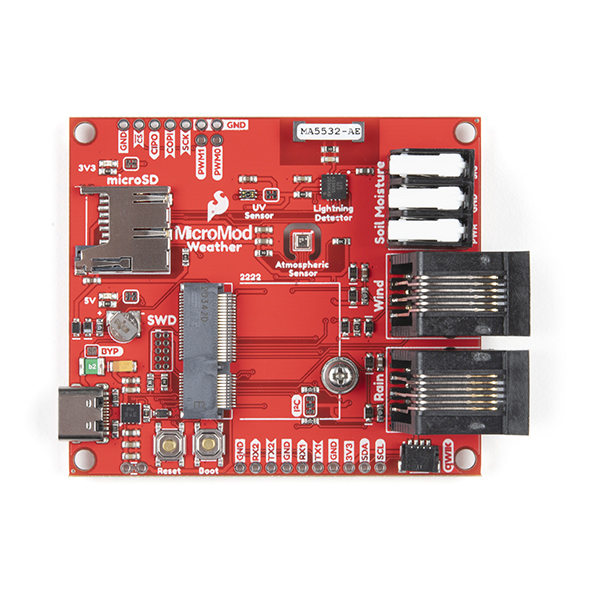
The MicroMod Weather Carrier Board is a peripheral for the MicroMod ecosystem that allows you to create your own weather station with one of a multitude of processors. The carrier board includes three sensors: the BME280 temperature, pressure and humidity sensor, the VEML6075 UV sensor and the AS3935 Lightning detector.
Along with these on-board sensors there is a 3-pin latch terminal to add an external soil moisture sensor as well as a pair RJ11 jacks to plug in the wind and rain sensors included with our Weather Meter Kit. To top it all off there is a microSD card slot so you can plug in an SD card to log all of that glorious weather data using the MicroMod processor of your choosing!
MicroMod is a modular interface ecosystem that connects a microcontroller “processor board” to various “carrier board” peripherals. Utilizing the M.2 standard, the MicroMod standard is designed to easily swap out processors on the fly. Pair a specialized carrier board for the project you need with your choice of compatible processor!
- Barometric Pressure/Humidity/Temperature Sensor - BME280
- Operated in I2C mode. I2C address: 0x77
- UV Light Sensor - VEML6075
- I2C address: 0x10
- Lightning Detector - AS3935
- Operated in SPI mode.
- 2 x RJ11 Connectors to connect Wind/Rain sensors.
- 3-pin Latch Terminal to connect Soil Moisture sensor.
MicroMod Weather Carrier Board Documentation:
- Schematic
- Eagle Files
- Hookup Guide
- Board Dimensions
- Hardware GitHub Repo
- BME280 Datasheet (PDF)
- VEML6075 Datasheet
- AS3935 Datasheet
Weather Carrier Board Sensor Arduino Libraries:
MicroMod Documentation:
SparkFun MicroMod Weather Carrier Board Product Help and Resources
MicroMod STM32 Processor Hookup Guide
May 13, 2021
Get started with the MicroMod Ecosystem and the STM32 Processor Board!
MicroMod nRF52840 Processor Hookup Guide
January 14, 2021
Get started with the MicroMod nRF52840 Processor following this guide.
MicroMod Weather Carrier Board Hookup Guide
January 14, 2021
A quick guide to help to create your own MicroMod weather station using the MicroMod Weather Carrier Board and Processor of your choice.
Core Skill: DIY
Whether it's for assembling a kit, hacking an enclosure, or creating your own parts; the DIY skill is all about knowing how to use tools and the techniques associated with them.
Skill Level: Noob - Basic assembly is required. You may need to provide your own basic tools like a screwdriver, hammer or scissors. Power tools or custom parts are not required. Instructions will be included and easy to follow. Sewing may be required, but only with included patterns.
See all skill levels
Core Skill: Programming
If a board needs code or communicates somehow, you're going to need to know how to program or interface with it. The programming skill is all about communication and code.
Skill Level: Rookie - You will need a better fundamental understand of what code is, and how it works. You will be using beginner-level software and development tools like Arduino. You will be dealing directly with code, but numerous examples and libraries are available. Sensors or shields will communicate with serial or TTL.
See all skill levels
Core Skill: Electrical Prototyping
If it requires power, you need to know how much, what all the pins do, and how to hook it up. You may need to reference datasheets, schematics, and know the ins and outs of electronics.
Skill Level: Rookie - You may be required to know a bit more about the component, such as orientation, or how to hook it up, in addition to power requirements. You will need to understand polarized components.
See all skill levels
Comments
Looking for answers to technical questions?
We welcome your comments and suggestions below. However, if you are looking for solutions to technical questions please see our Technical Assistance page.
Customer Reviews
5 out of 5
Based on 1 ratings:
Awesome weather carrier board!
Has everything a weather station should have. Not sure why the soil moisture input and UV sensor is there but what's 2 more data points to log. I'm putting this in a water proof box outside. No UV will get inside the box unless I open it. I'll be adding a 1-wire port for external temperature sensing. That would be a nice added feature in the next revision. I'm still developing my code for the ESP32 MicroMod processor for it but will soon upgrade my existing power hungry Onion weather logger processor.
It looks like this board cannot be used with the Micromod LoRA board, because there's no CPU on it. Is there a way I can't see to make this LoRA enabled?
Can you breakout some of the gpio pins
There are a few issues with this board when connected to the Weather Meter kit:
1) - as noted the values for the wind direction don't match those in the example code. This was the subroutine I ended up using:
You'll note there is no SSE - couldn't quite get that to work..
2) Nextly, the UV sensor on the board is acutely sensitive to the angle at which the light is striking it - so if you really want accurate data, you are going to need to rig up some sort of servo motor to follow the sun... Sounded like too much work for me.
3) Still on the UV sensor, just about any enclosure will wildly reduce the UV values. Tried all sorts of things - even cling film took a fair chunk out; although the error from not pointing at the sun (see 2) is much more significant.
4) The rain sensor 'bucket' switch bounces for 2-4 actual clicks per bucket - varies randomly so tricky to calibrate for. A 200ms debounce worked nicely for me:
With the accurate counting of ticks I found the rain sensor calibration was around 0.476
We have almost integrated this into Home Assistant using MQTT server - scope creep currently happily derailing project ;)
Not all sensors are the same...
I've been trying to use the MicroMod Weather Carrier Board with the sensors from a Holman weather station https://www.holmanindustries.com.au/product/aspect-wireless-data-centre-weather-station/
No matter what I did I could not get the anemometer to give a resistance output, either with the MicroMod Weather Carrier Board or directly with a multimeter. The wind speed sensor seemed to work, but didn't seem to be the right resistance for a reed relay.
So I pulled the sensors apart to have a look. From the outside, the anemometer looks identical to the one you sell, but the Holman sensors are now active. Photo of the anemometer internals: https://i.postimg.cc/Qx9thy4p/Holman-weather-station-anemometer.jpg
The 4 wire interface for this version is:
not connected
Vdd - 3.3v
DATA - Wind Direction output
anemometer pulse
GND
not connected
Obviously this sensor array does not work with your board :-(
Update: This sensor array has a serial data stream from the anemometer, protocol currently unknown. https://i.postimg.cc/QMXK8qWh/Holman-weather-station-wind-direction-protocol.jpg
Anyone try this with the XA1110 (Qwiic) GPS? I cannot seem to get it to read GPS data even though it "sees" the module.
Gaaack!
The MicroMod Weather Carrier Board is a PERIPHERAL, not a periphery!
s/periphery/peripheral/g
Thanks.
Fixed! I can't believe that was missed. Thanks for catching!
Been waiting for a Weather Board that works with Artemis, thank you!
Can you add to the Hookup Guide details about using an analog capacitive soil moisture sensor (such as DFRobot's Gravity Soil Moisture Probe dfrobot.com/product-2054.html my goto soil sensor these days) via the latch terminals G0/Bus0 and A0?
Better yet for V2 of the Weather Board is adding a jumper that bypasses the micromod connector to provide power directly from the voltage regulator to the latch terminal instead of G0/Bus0.