- Home
- Product Categories
- Development Tools
- 18 Pin PIC Development Board with Relays

18 Pin PIC Development Board with Relays
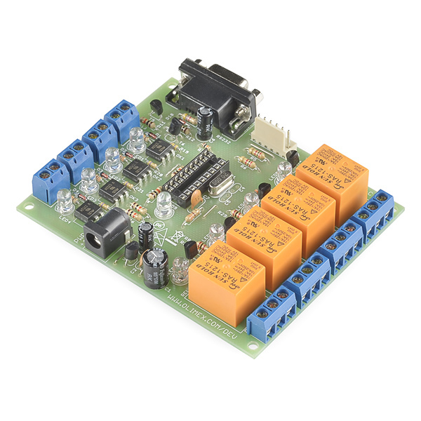
Development board for 18 pin PIC microcontrollers with power supply circuit, crystal oscillator circuit, RS232 port, ICSP/ICD port, 4 relay output, 4 optocoupler isolated inputs.
Note: An IC is not included, please check below for suitable ICs.
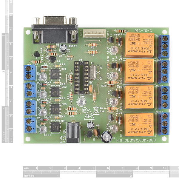
- FR-4, 1.5 mm (0.062"), green solder mask, white silkscreen component print
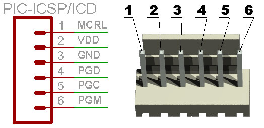
- ICSP/ICD connector for programming with PIC Programmers and Debuggers (for PICs with ICD support)
- Power plug-in jack for +12VDC power supply
- Voltage regulator +5V, 78L05 and filtering capacitors
- Status LED connected to RB5
- Quartz crystal oscillator circuit - 20MHz
- DIL18 microcontroller socket
- RS232 DB9 female connector
- RS232 interface circuit with Tx, Rx signals
- 4 optocoupler isolated inputs with screw terminals
- Input status LEDs
- 4 relay outputs with 10A/250VAC contacts with screw terminals
- Output status LEDs
- 3.9x3.15" (100x80mm)
18 Pin PIC Development Board with Relays Product Help and Resources
Core Skill: DIY
Whether it's for assembling a kit, hacking an enclosure, or creating your own parts; the DIY skill is all about knowing how to use tools and the techniques associated with them.
Skill Level: Noob - Basic assembly is required. You may need to provide your own basic tools like a screwdriver, hammer or scissors. Power tools or custom parts are not required. Instructions will be included and easy to follow. Sewing may be required, but only with included patterns.
See all skill levels
Core Skill: Programming
If a board needs code or communicates somehow, you're going to need to know how to program or interface with it. The programming skill is all about communication and code.
Skill Level: Competent - The toolchain for programming is a bit more complex and will examples may not be explicitly provided for you. You will be required to have a fundamental knowledge of programming and be required to provide your own code. You may need to modify existing libraries or code to work with your specific hardware. Sensor and hardware interfaces will be SPI or I2C.
See all skill levels
Core Skill: Electrical Prototyping
If it requires power, you need to know how much, what all the pins do, and how to hook it up. You may need to reference datasheets, schematics, and know the ins and outs of electronics.
Skill Level: Noob - You don't need to reference a datasheet, but you will need to know basic power requirements.
See all skill levels
Comments
Looking for answers to technical questions?
We welcome your comments and suggestions below. However, if you are looking for solutions to technical questions please see our Technical Assistance page.
Customer Reviews
No reviews yet.
Hello, I program the interface RS232. I'm surprised that this board haven`t MAX232. Is not it necessary? Thanks
Hello, I try the board with the classic pic16f84 and it work perfectly, but i'm try with pic18f1330 and i can't. Can i use this pic? I see the pinout and i don´t find any problem. PD: sorry for my poor english. Thanks
SOLVED. I need put de OSC to HS, not XT
well, I either have a dead 16F628A or my oscillator isn't working. I have no pulse on the either of the clock oscillator pins. Crap! should've ordered a couple of the PICs.
The schematic calls for a 12v supply. The related and recommended products below show a 9v supply. Is it know for certain that this supply is compatible with this board? Thanks!
Hm, I'm not sure why the 9V supply is listed below; the board will likely work fine with 9V, but since we carry it, there's no reason not to get the real thing: 12V Wall Adapter. Hope this helps!
Perfect. Thanks!
Sorry, one more question: I'm new to this PIC stuff. Will any 18-pin chip work, or do I need to use a specific chip?
Never mind, it looks like there are really only 2 choices, and that either one will work.
Anyone know if a PICAXE 18m2+ would work on this board? Assuming its been programmed before mounting ...
Hi just wonting to know can this item be programmed so that when it receives a trigger it will randomly fire 1 of the 4 relays for a pre set time then turn off the relay ready for the nest trigger and so on
Thanks
Yes, the hardware can easily handle this. But remember that you'll be the one responsible for writing the program, so you should already know (or be willing to learn) how to program a PIC.
hi, can you please tell me which PIC are you using? can i use pic 16f84 with the same source code?
Can the inputs be attached to simple single pull single throw switches to make a very simple four switch - four relay project (with 2^4 configs)? If so is an external pull-up/pull-down needed?
Unless you use SPDT switches connected to both VCC and GND, pullups are recommended. Internal pullups are available on some PIC I/O lines, so you may not need external ones. Check the datasheet.
Can this product be programmed with MPLAB ide?
Sure! But you'll also need a hardware programmer (I personally like the PICKit).
Thanks for the help MikeGrusin... I took your advice and purchased the PICKit like you recommended and it does not fit on this board. The packaging is too large and it will not connect unless I decide to take a dremel to the thing. Now I'm out $60 bucks. Also, the software that came with the programmer refuses to install but I'm going to ask Microchip about that.
Sorry about that - this board was designed long before the PICKit came out, and the PICKit does have an unfortunately large snout. What I've done in these cases is to stick an Arduino 6-pin header into the PICKit, which gives it another 1/2" or so of clearance, or make a quick extension cable out of M/F jumper wires. Regarding MPLAB, you might try downloading the latest version directly from Microchip, in case there was a problem with the CD. In any case, if you're unhappy with your purchase, please let us know at cservice@sparkfun.com and we'll make things right.
I'm not following your schematic regarding the optocoupler isolated inputs. Are they routed to nodes on the dual inline socket? Will this config give me the ability to program the chip so that voltage on a particular input can be read by the chip and then the relay tripped according to my code? Thanks.
Oops. My mistake. It's there. Sorry.
Greetings,
When using relay devices like this do you need to 'over specify' on voltage and current. Or, in other words, if I trigger a 250volt device drawing 5 amps 10 times a day will this device fail sooner than if say I had 500v/10amp relays? Thanks for your input, just trying to plan accordingly.