- Home
- Product Categories
- Sensors
- Triple Axis Accelerometer Breakout - MMA7260Q

Triple Axis Accelerometer Breakout - MMA7260Q
Replacement:SEN-09836. This IC has been retired and we are no longer making breakout boards for it. This page is for reference only.
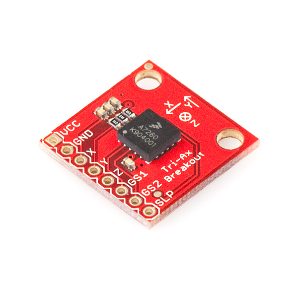
This is a breakout board for Freescale's triple-axis MMA7260QT accelerometer. With a low power shut-down mode, high sensitivity output with selectable ranges (±1.5, 2, 4, and 6g), this was one of the very first sensors to market with three accelerometers built onto a single IC! Board comes fully assembled and tested with external filters installed.
The MMA7260QT is a 3.3V part and outputs an analog voltage for each of the three outputs. This voltage is in ratio to the measured acceleration and to the supply voltage (ratiometric). You will need some extra hardware to convert this analog signal to a usable digital one. Luckily, many uCs have a built in Analog to Digital converter.
Not sure which accelerometer is right for you? Our Accelerometer and Gyro Buying Guide might help!
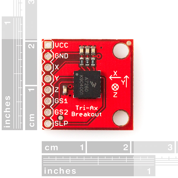
- 25x25 mm (1x1")
- Tri-Ax-Schematic-v01.pdf
- Eagle Files
- Tom Igoe's online tutorial using the MMA7260Q!
- Portuguese tutorial by Daniel Gonçalves!
Comments
Looking for answers to technical questions?
We welcome your comments and suggestions below. However, if you are looking for solutions to technical questions please see our Technical Assistance page.
Customer Reviews
No reviews yet.
This is my first time using an accelerometer...I'm having issues...I'm using the arduino hooked up this way...
VCC,SLP - 3.3v
GND, GS1, GS2 - GND
x - analog 0
y - analog 1
z - analog 2
The data that I am reading into the serial monitor is all over the place, even when I'm not moving the accelerometer....when I try doing noise reduction by averaging rapid readings...i get a pretty steady 460-500 for all axis, moving or not. any ideas?
I also got the noise issue, and tried many ways, changing the wire length, twisting them together, having extra filers....
Finally, I have just decided to take the average of the readings and that gives me a +/- 3 uncertainty compared to +/- 20 from before.
Hope this help
Just completed and posted a project using this accelerometer. The information can be found here:
http://digitalstew.blogspot.com/2010/09/trashcan-accelerometer.html
Great sensor, easy to interface with an Arduino.
Check out this alternative - has 3.3v regulator and G-Select pull-ups integrated, and $5 cheaper - http://www.pololu.com/catalog/product/766
Does the accelerometer become permanently damaged if I accidentally hook it up to the Arduino 5v line?
I have gone through 3 of these things... Im hooking them up to 3.3v and I'm still getting nothing.... Tried to read on the O-scope. I get a spike then nothing. Do I need to tie the selects to vcc or gnd?
Don't forget to connect the sleep pin to Vcc to enable the chip. If this pin is unconnected or taken to a low state, this chip sleeps.
Is it possible to use Triple Axis Accelerometer Breakout - MMA7260Q in an autonomous helicopter project to achieve a hover. If it is can you guys just give me a basic idea?
Thank you
Sure- first define the hover, i.e. bring the helicopter at the desired angle(preferably parallel to the ground) and tell your microcontroller to store the X,Y,Z values from the accelerometer. Then tell it to read new values every, say, 10 milliseconds, compare them to the ones it has already stored and make adjustments (move the servos) until they're dead on. What puzzles me however os the fact that most manufacturers use gyros in helicopters... I wouldn't try this method with any helicopter before I confirmed it's been tried and tested. I've never tried it, in fact I just thought it up.
Accelerometers are not a good choice to maintain pitch, yaw or roll in an aircraft. Gyros need to be used for this. An accelerometer provides half of what you need.
The main issue is that the accelerometer measures the acceleration in xyz relative to the board, not the ground. You could very easily have the helicopter pitched up or down and still maintain 1g in the z relative to the board. If your helicopter is pitched over and maintains 1g in the z, contact with the ground will happen eventually.
An EDIT-AFTER-POST function would be great in the COMMENTS. (I know that there is a PREVIEW button!)
What I meant to type was :
yes the breakout-board has proper .100 hole pattern.
What gets me is that the signal is maintained.
What I mean is that as rotated along the X or Y -Axis, the X-or-Y signal is maintained.
If I rotate along the X or Y -Axis, the output is maintained after motion stops.(Z-Axis is not maintained)
The device acts more like a 3-axis pseudo-gyro. I would expect an accelerometer to go to zero whenever motion is stopped.
My breakout-board does NOT do this(zero signal on stopped motion,) but that is OK for my application. Actually, this is great for me.
Yes, the output will be "maintained" after you finish turning. What you are measuring at that point is acceleration due to gravity. A gyro will go to zero, since it measures rate of change of angle, while an accelerometer will not, since it measures net acceleration, which includes gravity.
I'd like to be able to mount this to a circuit board -- is there any way to get the pin and hole locations so I can make it a part in EAGLE?
Eagle Files are up. They should be a good source for the dimensions and pin locations.
-techsupport at sparkfun dot com
Thanks, but I'm stuck on Eagle 4.16 (no newer support for X Windows or "old" OS X) so I can't open them. Regardless, I'll have the part soon and will be able to measure it -- it's just 1"x1" with a 8-pin 0.100 row of pins and two holes anyway.
jolshefsky: Thanks, but I'm stuck on Eagle 4.16 (no newer support for X Windows or "old" OS X) so I can't open them. Regardless, I'll have the part soon and will be able to measure it -- it's just 1"x1" with a 8-pin 0.100 row of pins and two holes anyway.
yes the breakout-board has proper .100 hole pattern.
What gets me is that the signal is maintained.
What I mean as that the rotated along the XorY-Axis, the XorY signal is maintained.
If I rotate along the XorY-Axis, the output continues to be maintained after motion stops.(Z-Axis is not the maintained)
The device acts more like a 3-axis pseudo-gyro. I would expect an accelerometer to go to zero whenever motion is stopped.
My breakout-board does NOT do this(zero signal on stopped motion,) but that is OK for my application. Actually, this is great for me.