- Home
- Product Categories
- Development Tools
- 28 Pin AVR Development Board

28 Pin AVR Development Board
Replacement: None. We are no longer carrying this AVR development board in our catalog. This page is for reference only.
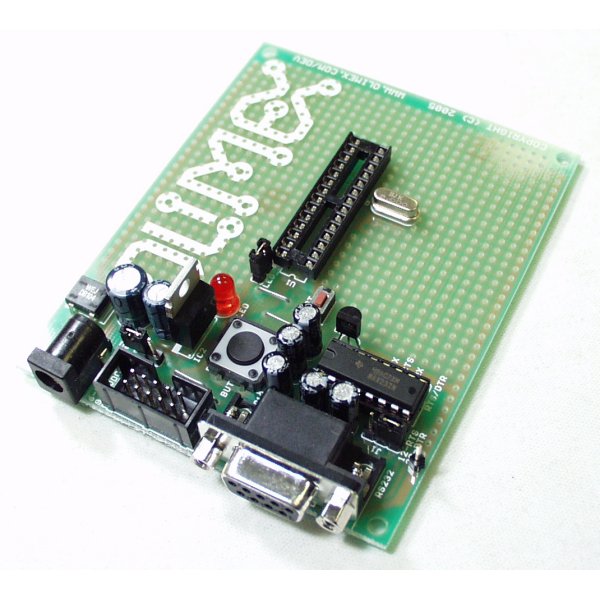
This prototype board for 28 pin AVR microcontrollers includes a power supply circuit, crystal oscillator circuit, RS232 port, reset IC, status LED, and 10 pin STK ICSP port.
Note: Board does not come with AVR installed. Please see a list of related items below.
- STK200 compatible ICSP 5x2 pin connector for in-circuit programming with AVR-PG1 or AVR-PG2
- RS232 Tx, Rx interface with MAX232 IC on socket
- 8 MHz crystal on socket (user replacable)
- Reset IC ZM33064
- Reset button
- General purpose push button
- Status LED connected to PC5 via removable jumper
- DIL28 microcontroller socket
- Power plug-in jack
- Selectable +3.3V / +5V power supply voltage regulator
- Extension pin headers for each uC pin
- Four mounting holes 3.3 mm (0.13")
- Vcc and GND bus
- 100x80 mm (3.9x3.15")
28 Pin AVR Development Board Product Help and Resources
Core Skill: Programming
If a board needs code or communicates somehow, you're going to need to know how to program or interface with it. The programming skill is all about communication and code.
Skill Level: Competent - The toolchain for programming is a bit more complex and will examples may not be explicitly provided for you. You will be required to have a fundamental knowledge of programming and be required to provide your own code. You may need to modify existing libraries or code to work with your specific hardware. Sensor and hardware interfaces will be SPI or I2C.
See all skill levels
Core Skill: Electrical Prototyping
If it requires power, you need to know how much, what all the pins do, and how to hook it up. You may need to reference datasheets, schematics, and know the ins and outs of electronics.
Skill Level: Noob - You don't need to reference a datasheet, but you will need to know basic power requirements.
See all skill levels
Comments
Looking for answers to technical questions?
We welcome your comments and suggestions below. However, if you are looking for solutions to technical questions please see our Technical Assistance page.
Customer Reviews
No reviews yet.
User manual says max 12v input..but datasheet for the LM317 says max 40v? Looking in to use this in a car, so supply would be about 14,7 V. I guess it should work up to 15 V?
Sorry for the noob question, but can I use this to program an atmega328 with the arduino IDE, using an RS232-USB cable? Please someone reply ASAP.
Oh, and in case you're wondering, I need to use it just as the programmer, as the board is too big for the enclosure I'm using.
nevermind, it was just a stupid question, and I figured out I could use another programmer designed for that, I wish I could delete comments
You can buy a better board with a lot more flexibility built into the design from http://www.protostack.com/boards/microcontroller-boards/atmega8a-development-kit. I bought two and I truly like the space and the design of the board. Sparkfun is a great place to find things that the other suppliers don't provide, however from time to time, there are other small scale designers that make your day and this one such instance, where a true Arduino compatible board with a lot of proto-space that is also very cost effective, is available.
Converting Olimex AVR P28B to Arduino:
* Preface. I would prefer something similar to the Prototino (kind of expensive for a stripped board) or the Protoduino but with serial hardware (these would be a good choice for non-serial projects). Since these lack it, the Olimex board is a good alternative. A ProtoShield soldered in could work, but it is kind of expensive for a stripped board, and I don't like the breadboard type hole connections. Whatever I chose would require work, but the Olimex board required the least for the price.
* Add ATmega328 (or ATmega168 for older designs; other ATmega's could work with custom boot loaders).
* Swap clock to 16MHz (or 20MHz with custom boot loader). If keeping the 8MHz clock, the "Lilypad" setting may work for flashing, but I haven't personally tried.
* Wire up serial. Set DTR jumper (DB9 pin4). AVR pin1: 100nF to 232-DTR. AVR pin2: 1k resistor to 232-TX. AVR pin3: 1k resistor to 232-RX.
* ICSP-6 to ICSP-10 adapter: miso 1->9, vcc 2->2, sck 3->7, mosi 4->1, reset 5->5, gnd 6->4,6,8,10. Pin1 of the ICSP-10 header is closest back to the DB9 connector. Steps. Stick the 10 pin header in the socket and strip and tin the leads of 6 wires (2-3" worth). Make pin 6 ground and bend the other pins (4, 8, 10) over and solder them to pin 6. Ignoring pin 3, solder the wires to the 10 pin header. Solder the wires to the 2-4-6 pins of the 6 pin header. Solder the wires to the 1-3-5 pins of the 6 pin header (mine was a single row header, I soldered them backwards and did a quick twist). Tape up any exposed pins and the connectors if they are 1 row headers. Be sure to mark pin 1 positions on both ends of the adapter.
* LED. If an extra LED is needed for the project, just leave it and wire in a separate Arduino LED. Un-jumper and rewire LED to AVR pin 19 for Arduino inverted operation (the LED is wired backwards compared to normal Arduino). For normal operation, unsolder R2 and the LED and solder them to AVR pin 19 (LED pointing towards ground). If R2 is too small to handle, use a regular 330-560ohm resistor. The left over jumper can also be unsoldered and used elsewhere.
* BUTTON. R6 is a 10k pullup resistor to AVR pin 4. If this is undesired, remove it and don't press BUTTON. BUTTON can be unsoldered along with R6 and used elsewhere.
* C13 (capacitor to AVR pin1-reset) is empty pads and should generally be left that way.
* The Olimex board can communicate with a standard PC serial port or use a standard DB9 USB serial cable (cheap).
Ok hw gurus, here's your chance to help out a clueless sw guy:
I'm using this board essentially as a power supply and rs-232 converter for another circuit that I've built on the board.
Here's the problem. The board doesn't talk to the PC unless I put an RS-232 mini tester (w. leds for the serial lines) on the line. Then the RS-232 works and communicates with a PC. With no tester, it doesn't work.
Any ideas? I am using the board in 3.3v mode (my circuit requires 3.3v).
Thx!
it was fairly easy for me to make one of these so that it could either behave like an arduino (with the serial port hooked up like a max232 freeduino) or like a serial programmer. i have a big switch to flip between the modes. i added a zif socket in parallel with the socket it comes with and i use the non-zif socket to connect up wires when i'm doing simple arduino-style projects.
as others have said, the max232 is just sitting there. you have to hook it up yourself, even though it looks from the traces that such things should have been done for you.
Totally digging up this old thread, but if anyone was still curious about the ZIF socket if you bend the jumper for the LED connection down a bit you can fit a PRT-09175 28 pin ZIF socket into the dev board. The ZIF socket will fit over the crystal, however you will not be able to remove/replace the crystal with the ZIF socket in. Also, an atmega328p is pin compatible with this dev board.
Currently using this board with a ZIF socket, atmega328p, and Olimex STK500 USB programmer (PGM-08702). Just as a note though, I have had some dev boards where the ISP connection provides enough power to program the chip. This board requires external power applied even with ISP hooked up to program.
AcidBlue. Did you ever acidblue: Has anyone been able to fit a zif socket on this board?
It seems the jumper and resonator would be in the way.
Also is this board compatible with the atmega 168 and 328?
Was thinking of using this board upload boot-loaders into
bare atmega chps.
Have you tried it yet? I need to do the same thing and had the same idea.
Luceroz: Holy CRAP! The Max232 is NOT wired to any pins of the avr by default.... I've been beating myself trying to get serial working on the board -- under the very stupid assumption that the max232 was already wired up. PLEASE DONT BE AS RETARTED AS ME. On a related note, I can flash my atmega328's using an olimex parallel stk200 type programmer with ease on this board. This is one of those all-too-familiar situations where I wonder if my brain is wired correctly.
Is that what was wrong man I gave up on mine cause I couldnt get mine to work.
Has anyone been able to fit a zif socket on this board?
It seems the jumper and resonator would be in the way.
Also is this board compatible with the atmega 168 and 328?
Was thinking of using this board upload boot-loaders into
bare atmega chps.
any change of a usb version in the future?
I may be missing something obvious (new to this stuff!) but...
To use board in 3.3V mode (with the 3.3V jumper made) you have to disable U3 - low voltage detector (I just removed mine) otherwise it just holds the AVR in reset.
Also, the schematics on this site and on Olimex site are different, and both are different to the board that I have received!!!
Holy CRAP! The Max232 is NOT wired to any pins of the avr by default.... I've been beating myself trying to get serial working on the board -- under the very stupid assumption that the max232 was already wired up. PLEASE DONT BE AS RETARTED AS ME.
On a related note, I can flash my atmega328's using an olimex parallel stk200 type programmer with ease on this board.
This is one of those all-too-familiar situations where I wonder if my brain is wired correctly.
From the schematic, it looks like it should work for Atmega8. Any reason why it does not? I would love to use this for my Atmega8 projects.
From the PDF labeled avr-p28b.pdf listed above the comments:
Supported devices:
AT90S2333, AT90LS2333, AT90S4433,
AT90LS4433, ATtiny28L, ATtiny28V
microcontrollers.
Does anyone know if this board supports all 28 pin AVR's?