- Home
- Product Categories
- Other LEDs
- SparkFun LED Matrix - Serial Interface (Red/Green)


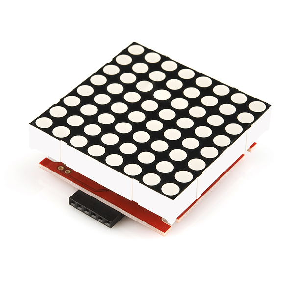
SparkFun LED Matrix - Serial Interface (Red/Green)
This is the medium sized LED Matrix with a backpack that has been designed to take SPI serial input and display any graphics you pass it. All the refreshing and communication control is taken care of by the backpack. It's even reprogrammable! Off, Red, Green, and Yellow colors are available.
Unit comes with an Red/Green Matrix assembled with a RG Matrix Backpack Controller.
Check out the LED Coffee Table tutorial!
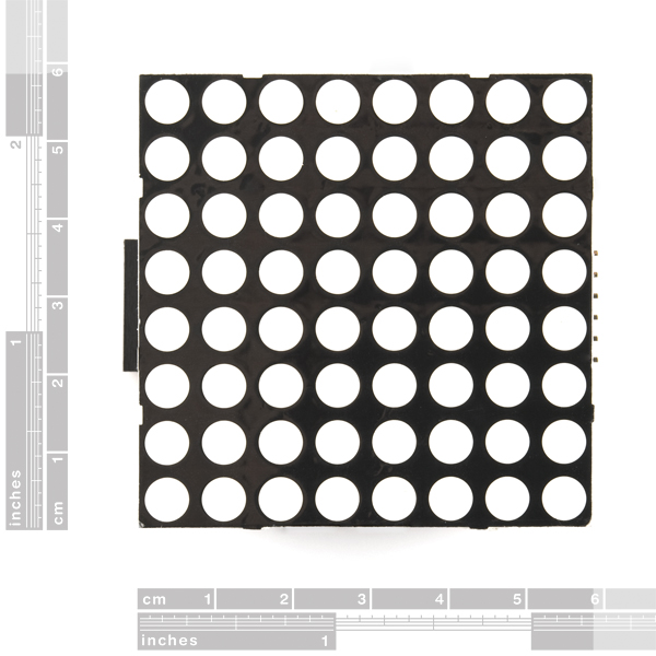
- 2x2" square
Max width of backpack including connector pins - 1.0"
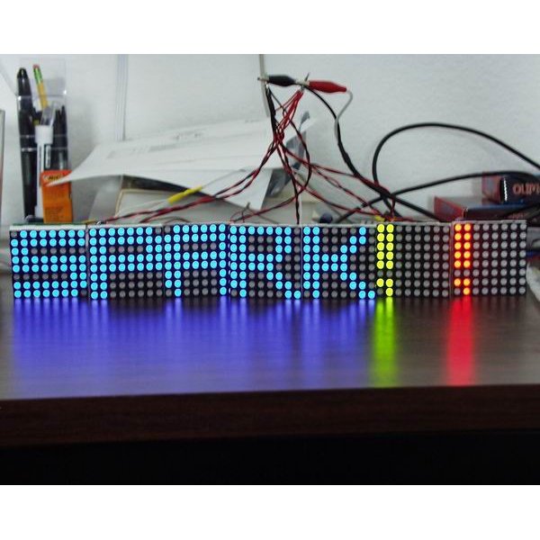
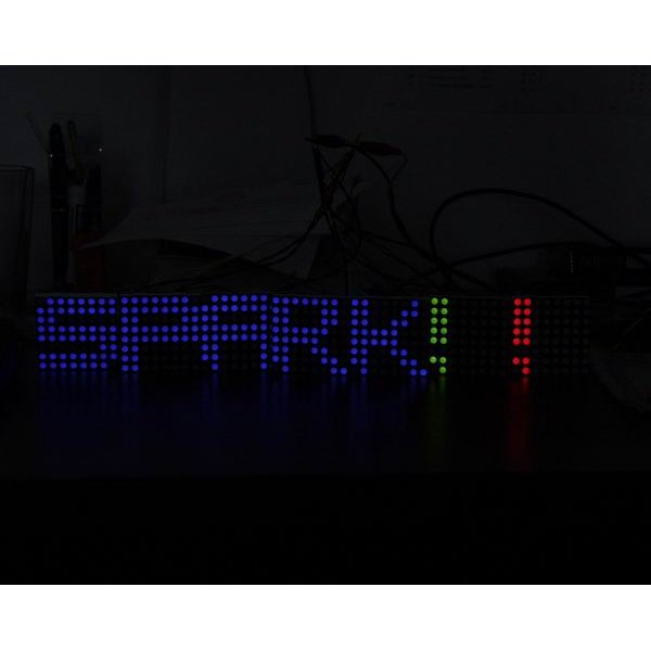
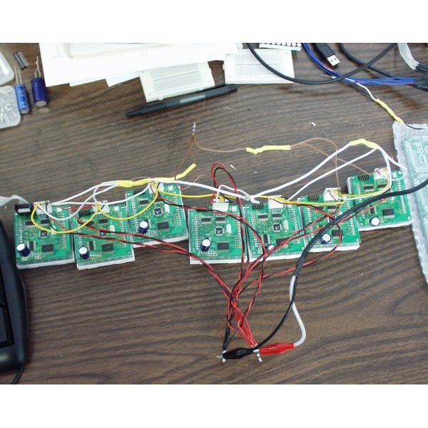
Pictures show an example array of RGB matrices. These units do not have the Blue color available.
SparkFun LED Matrix - Serial Interface (Red/Green) Product Help and Resources
Core Skill: Programming
If a board needs code or communicates somehow, you're going to need to know how to program or interface with it. The programming skill is all about communication and code.
Skill Level: Competent - The toolchain for programming is a bit more complex and will examples may not be explicitly provided for you. You will be required to have a fundamental knowledge of programming and be required to provide your own code. You may need to modify existing libraries or code to work with your specific hardware. Sensor and hardware interfaces will be SPI or I2C.
See all skill levels
Core Skill: Electrical Prototyping
If it requires power, you need to know how much, what all the pins do, and how to hook it up. You may need to reference datasheets, schematics, and know the ins and outs of electronics.
Skill Level: Rookie - You may be required to know a bit more about the component, such as orientation, or how to hook it up, in addition to power requirements. You will need to understand polarized components.
See all skill levels
Comments
Looking for answers to technical questions?
We welcome your comments and suggestions below. However, if you are looking for solutions to technical questions please see our Technical Assistance page.
Customer Reviews
No reviews yet.
obtained 3 LED Matrix Controller PCBs as a Ding and Dent Product... just the bare pcbs...
Please update schematic. You are shipping v08 of this board, the schematic indicates v03.
Thanks,
Justin
Warning: SparkFun "resistorless" design tends to fry led matrix in a few hours in continuous use. I bought 3 of these. 2 led matrix does not survive an hundred hours of working (approximately 10h/day for 10 days). The third display continues to working now, after several hundred hours. I also had several trouble to eliminate the ghosting issue. I solved not daisy chianing led matrix but driving them independently (yes, waste of I/O on the microcontroller, but was the only solution that worked)
Why have the LED current limiting resistors been eliminated from the most recent schematic? I'm just trying to understand why they are not needed? Thanks, Carl
Please update product images and downloadables to current version (no v. info printed on board but it's not v08n anymore).
Svealebor's pastie'd code with some changes (e.g. rowmap) works for me.
I just got an Arduino Leonardo R3 experimenter (20-013-134) set from Amazon.com that has an 8x8 led matrix and a four digit 7 segment display by SainSmart.com. They are both dumb and I need your backpacks to make them smart. I did not see a backpack for your Led matrix or the 7 segment display. Do you have backpack for these that I can buy? I upgraded all of my LCDs to ones with color backlights and I use your LCD serial backpack for all of them. I love your backpacks and breakout boards. These people also have 3D printer brain kits that I have never seen before. My kit also has an ultra sonic range finder, an MP3 player infrared remote control with receiver chip and a prototyping shield.
I had a look at the Matrix Backpack Controller firmware, but it does not seem to support the % command. Am I right? I'm trying to have some text scroll on two display, but my code makes the display flicker. The reason is that every time I write to the display, what was in there shifts left, which generate the flickering. Any suggestions? Thanks, Alex
Why no current limiting resistors? After doing some calculations, it would appear that the voltage across the LEDs is way to high. The only thing that I can think of is that the software running on these is pulsing the LEDs. Turn on the row, small delay, Turn off the row, large delay. Repeat for all remaining rows. Is this a far assumption? Doesn't this reduce the life of the LEDs? What happens if the software crashes?
So I just got 2 more of these and am trying to daisy chain them together. I'm trying to make my best guess using the RGB examples out there, but I can't even find any confirmation that these RG matrices daisy chain "out of the box".
I'm trying the following code in the setup, for 2 boards, per the documentation:
However, it's not working when sending 128 bytes in the loop() part of the code.
Anyone have advice for daisy chaining the RG Backpacks? Thanks!
** Update 3/10/2012 **
I have this working on two screens, but now I'm having a ghosting issue. Please see the forums at http://forum.sparkfun.com/viewtopic.php?f=32&t=31590&p=140963 for more info.
** Update 3/18/2012 **
Ghosting issue has been resolved. Please see forum linked above.
Does anyone have any working Arduino code for the Red / Green only backpack? I'm a little disappointed that this isn't working as easily as I thought it would.
Hi Mark, Do you still need some example code?
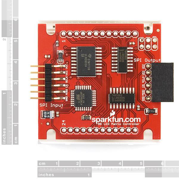
Also, as noted above by Skaros, this board has an error. Use the 'SPI Output' connector as the input and 'SPI Input' as the output and it works fine. They mixed up the MISO and MOSI signals.
Jim
Hi Jim. Thanks for the reply. I actually FINALLY did get it (kind of) working. I'm using the code on the Arduino Forums at http://www.arduino.cc/cgi-bin/yabb2/YaBB.pl?num=1236098804, with the connections as you and others have noted.
I'm still having an issue though. My code will only work if the power line (Vcc) is floating. If it's plugged into 5V on the Arduino (NG) power rail it will not work (Arduino is running on USB power). If I unplug the power line, the matrix will light up with the programmed pattern, and then if I re-plug Vcc into 5V the pattern gets brighter.
I just updated the code to display an alternating pattern, which will work with Vcc floating, but the moment I plug it into 5V on the Arduino the pattern stops alternating.
Has anyone seen that or have any ideas?
Hi Mark, I only needed a big red/green LED, so I set all values to the same data. It should not be too hard to update the code for patterns instead. I also use only USB power. With an external supply it uses about 250mA. Your USB port needs to be able to supply at least that. Here is my trivial test code for a simple all LED color, red then green.
Thanks for your help Jim. That code works great. I just tried a 9V, 600ma wall wart power supply and it's the same story. Code won't show up with Vcc on 5V. If I unplug it then LEDs light up and animate. When I plug Vcc back in, then the LEDs get brighter, but the animation (red/green blink) stops.
I'm stumped right now.
*** update ***
The above issue does not occur on my Arduino Uno. So there's something going on with my Arduino NG...
*** update ***
Here's a little video of it working side-by-side with a Processing sketch. I'll update the video page when I have some code to post that goes with it.
http://vimeo.com/37033773
Hey Sparkfun, just wanted to let you guys know that the MISO and MOSI pins on the SPI headers for the RG Matrix backpack are switched around. The "input" header should have MOSI instead of MISO. The schematic is also incorrect.
I picked one of these up a few weeks ago for a project and couldn't figure out why it wasn't working. I ran a wire to the other header of the backpack and it works fine, but this works terribly for any sort of backpack daisy-chaining.
Might consider buying it, if I could see PCB from both sides or have a look @ Eagle files.
Sry, me posting again - on which legs does it use the decoupling capacitors, on both 74hc595 and uln2803? Thank you wery much. I hope to get a replay from your team :)
Placing decoupling capacitors across the power lines near all logic components is standard design practice. If you look at the above schematic, you'll see decoupling capacitors drawn near most of the parts. These capacitors are located nearby the same parts in the physical layout. The transistor array has bulk and decoupling capacitors near it as it is switching large currents to the LEDs at high frequency. These capacitors prevent voltage spikes from propagating to the rest of the logic circuitry.
Thank You for your kind and educational answer. I am more than pleased :)
There are also no decoupling capacitors in 74hc595 or uln2803 sample applications in manuals.
Why does it have decoupling capacitors next to the ULN2803, it's an transistor array and you don't decouple transistors ...
This looks like an interesting project, but I wonder if it would be beneficial to have a choice between internal and external sync for multiplexing?
With a large array of such matrices, I would expect the EMI spectrum to be pretty gnarly if every module is "doing it's own thing."
I am in favor of using a distributed synchronization clock for all LED row/column scanning, and would appreciate any thoughtful comments about this suggection.
Can someone please show me the connections for this board with the Arduino Duemilanove?
Thanks!
it's the same methode with http://www.sparkfun.com/products/760
but the pin are not in the same place.
Philippe
Hi I'm a newby
Have just bought an arduino and this matrix. would like to make a simple scrolling clock with them. I cant find a library for this anywhere. Can anyone point me in the right direction?
Thanks
I've got some wiring examples that show Ground, SKC, MISO, MOSI, CS and +5V pins.
But my backpack has Ground, MOSI, CS, SCLK, VCC and VCC pins... can someone help me figure it out?
Is it possible to fade the brightness level of each LED? Can we make more than the default 3 colors?
What would be the cheapest way to go about getting the front of these to be touch sensitive?
Why there are TWO vcc pins for the SPI in/out jumpers?
Could you run this at 3.3V instead of 5V? Understand ATMega @ 16 MHz isn't officially rated for 3.3V, but I have used them over clocked and they work fine. I assume the LED matrix would be dimmer and consume less power which is fine for my application.
if I would make dot matrix 32x32.what avr 8535 40 can be used as controllers?
how do I use this product to support my project?
how the schematic?
The LED Matrix I recieved uses an Atmega 168 while the sample code seems to be written for Atmega 8 with an old version of the gcc-toolchain. I updated the self-control firmware example like thus:
http://pastie.org/321922
I agree, eagle files would be very cool. :)
Eagle Files?