- Home
- Product Categories
- GPS
- GPS Evaluation Board

GPS Evaluation Board
Replacement: None. We are no longer building this board but check out the rest of our GPS category. This page is for reference only.
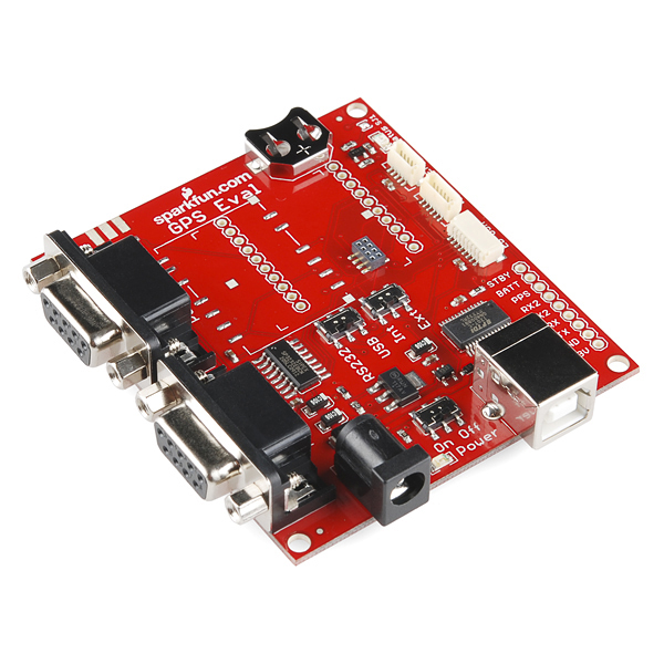
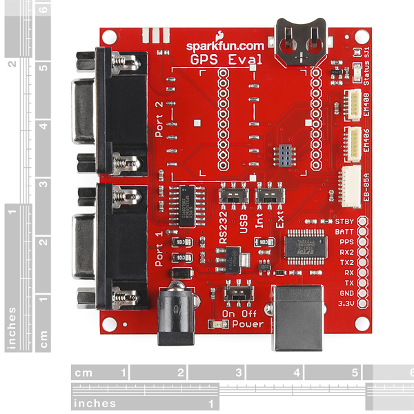
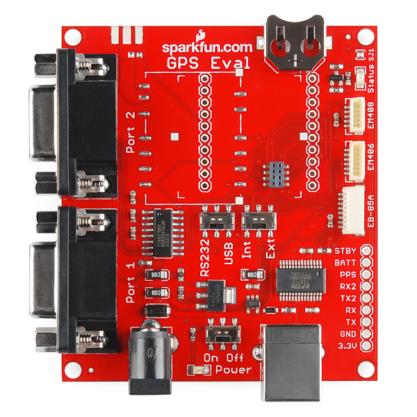
This is an evaluation board for our various GPS modules that incorporates many new features! This one board supports connection to the various GPS modules sold by SparkFun. Serial interface for USB over the FT232RL and a classic RS232 interface. Power is provided over USB or a DC barrel jack. A power switch, port selection, and serial isolation switches are available.
Check out our GPS buying guide!
Note: If using the Lassen iQ module, a piece of tape is needed to cover the exposed header under the module.
Supported Modules:
- FV-M8 (formerly EB-85A)
- EM406
- EM408
- Lassen iQ
- Copernicus (requires female socket installation)
- On board 5V regulation
- Power over USB
- Power over 5.5x2.1mm barrel jack (center positive)
- Status LED
- 12mm Coin Cell backup battery holder
- Serial over USB (FT232RL VCP)
- Serial over dual RS232 connection
- All serial ports broken out
- Schematic
- [Eagle Files](http://cdn.sparkfun.com/datasheets/Sensors/GPS/GPS Eval B-v20.zip)
- Dimensional Drawing
- Mini GPS Software
- GPSTrace Software
- Trimble GPS Monitor (for Lassen iQ and Copernicus)
Comments
Looking for answers to technical questions?
We welcome your comments and suggestions below. However, if you are looking for solutions to technical questions please see our Technical Assistance page.
Customer Reviews
No reviews yet.
Can anyone give me some guidance as to why I can only get GPS output when I power this over the USB port?
I'm assuming that this has a regulated 5v feed, so I can give it a supply voltage of maybe 5-12v on the barrel. I've tried with a 9v and 7.4lipo, and the power led is on, but no output from the GPS.
Hi, Could someone sell me (new or used) a Trimble Lassen iQ module? If so, please contact me: dweb at slabs.com.ar
Thanks in advance!
Hi all.
I have attached an iQlassen ( with a required piece of tape for isolation ) an 3v3 active antenna. The board powered from USB.
I am getting absolutly nothing from the receiver.
a) from a USB used to power on. b) from COM1 with pin-pin and cross serial cable.
i tried: minicom under GNU/Linux Trimble monitor under Windows XP hyperterminal
any advice are well come.
thx best regards, julio menezes
Dear All
My iQLassen is working. 1- powered thru barel connector +5V center pin 2- NMEA use port 2 at 4800,N,8,1 pin2=Tx pin3=Rx 3- TSIP use port 1 at 9600,ODD,8,1 important ODD, pin2=Tx pin3=Rx
My problem now: I am trying to get raw measurmentes ( carier phase,... ) I set ID=0x35 packet byte 3, bit0 to 1, enable raw. I sent (byte0=0x03,byte1=0x03,byte2=0x00,byte3=0x01), TSIP=
the receiver should return 0x55 packet but it did not.
1- Does anyone has successfully get raw measurements from iQlassen or Copernicus ? 2- could the 0x35 be turned off ( firmware ) ?
regards,
julio menezes PS: I am developping under GPL.
False Advertising! The picture shown for this product has the circuit board color as GREEN. But when I got the board, the circuit board color was and still is RED! Fix the picture!
dear sir where can i have the full tutorial to used this board and communicate it to pic microcontroller as tracking system for my crawler robot.
I see only 3.3 VDC support.
So this means this specific baord will not work with earlier +5 Vcc GPS boards?? Such as the old 8-channel Motorolla OnCore?
Does anyone know the operating temperature range of the GPS eval board?
I've made a list of components based on the schematic and looked up the operating temperature ranges of each component. I'm not sure if my list is complete or I've found the appropriate datasheet. Comments are encouraged to help me complete the list.
Item Min_T (degC) Max_T (degC)
I'm not sure if this has the LM1117 or the LM1117I. The LM1117I has a minimum temperature of -40degC whereas the LM1117 has a minimum temperature of 0degC.
Sources
At first enthusiastic about this board, after testing it for several days I am slightly disappointed. My application is/was to build a PPS-synchronized stratum 0 reference clock based on a EM 406a for a Linux system, connected via serial interface. It now works reliably but the board made it much more difficult than required to get there.
Printed notations like "PPS" on soldering connectors of the GPS-08334 made me believe that the GPS receiver's PPS signal can be grabbed there. However, this is true only if you connect an EB-85A, but NOT for the EM 406A, so I ended up in soldering a wire to the SMD-mounted connector pin 6 of the EM 406A, this being the only way to connect to the 406A PPS signal. Assuming this is an eval/prototype board, I really miss soldering contacts to connect to unused RS 232 or GPS connector pins.
The following extensions/improvements might be helpful for future releases (really miss them and think that a prototype/eval board should have them):
- on-board soldering pins/holes for ALL unused/non-connected RS232-connector and GPS receiver connector pins, particularly the EM406A PPS pin and the RS232 DCD pin (1), where the Linux drivers expects the PPS signal.
- An on-board LED connected to the PPS signal, flashing on PPS
- Connectivity for +5V (see below)
- For correct functionality, the EM 406A PPS signal must be processed (the PPS pulse is too short to be noticed by the RS232 interface on most computers). I've implemented it using a NE555 which is triggered by the PPS signal - it might be worth evaluating such extra functionality on board of the 8334. Btw, connecting to +5V for the NE555 required to solder to the backside of the board, as only +3.3V is available onboard.
I am convinced that these minor improvements could substantially improve the board's usage. Any thoughts on this?
I just received red color pcb version. it was changed 12mm coin cell backup battery holder position from left to right.
This change make i can't solder right side female socket.
Battery holder cover female socket space.
I tried to pare female socket's plastic part, pin was exposed.
Pin can be touch with battery holder.
What can i do for it?
Hi,
I've established communication over the USB port with ease, however, I would like to communicate via the tx/rx pins.
So far, I have had no luck connecting the serial tx/rx to my arduino and receiving data.
Is there a trick to transmitting and receiving data w/o a USB?
No status light when the EM408 is plugged in. I wonder if the board doesn't hold and Enable/Disable at 3.3 V?
I too can not get the EM408 working on the eval board. I have been able to get it working on a bread board by hooking up the Rx input to Vcc with a 470 ohm resistor. Also connect Enable/Disable to Vcc. With baud set to 4800 I am able to record NEMA sentences. Still, would like to use it with the board. Any ideas?
Is there any way, with either this product or something else on Sparkfun, where I can send a serial signal to a microcontroller so i can decode gps signals to be displayed on an LCD?
Just wondering because I want to make a backpack (like a daypack, not auduino extension) that has an on-board microcontroller. This would allow me to control flexible PV Panels from powerfilm to charge electronics as well as operate additional extensions such as GPS, internal LiPo charger, weather data, etc.
This board works like a champ with an EM406 module but I get nothing from my EM408... hmmmm some docs or even notes would sure help
Have you verified both modules are working outside of the eval board?
Also, if you are using a DB9 cable for RS232, use a straight through cable. A Null Modem cable will not work as the Tx and Rx wires are swapped. (I tried it for fun just to see.)
Got the board and used with an EM406a GPS chip. Works like a champ. Connected both to the RS232 ports and USB. Had better success using the SiRF demo software (See the EM-406A page). The SiRF demo includes the drivers for USB to serial. Also could see data using Br@@ys Terminal software set at 4800 baud across RS232. Didnt try the USB on Br@@ys. Would like to see the PPS pin on the EM406 connected to the Status led on the board. Other than that, it works well.
User robogiff reported problems when using a Trimble Lassen iQ GPS module. Problem was traced to the module casing shorting some of the vias that are exposed under the module. Putting tape on the underside of the module was effective in insulating the module and getting the eval board to work. This might occur with some of the other GPS modules, too.
Does this board work with sparkfun gps FV-M11??
is there a guide that comes along with how to use this??
I seem to have connected the necessary cables... but nothing happens...
I have inherited what appears to be an obsolete SparkFun Copernicus GPS RS232 Eval board (date code 10-2-06). Its two serial port connectors are too close together to attach to both simultaneously with standard cables. From the dimensional documentation it does not appear this problem has been fixed in this version of the board. Please clarify.
Just an update. Was able to get the board to work with an ancient laptop with a DB9 port. Have narrowed it down to possibly an errant driver for the USB to serial converter. Seems that Port 2 on the card is for NMEA output.
What's the secret to getting this evaluation board to work with the Copernicus DIP module? The computer recognizes the USB port, power gets to the board by
the red LED lighting. I have the 4800 speed set in
the COM 5 port. I have an antenna plugged into the SMA
connection. The switches are set correctly I think to
USB / INT. I don't have a coin battery for it yet but I don't think that is needed to get the thing to run. Do
I have a bad board?
Kurt