- Home
- Product Categories
- RFID Readers
- SparkFun RFID Reader Breakout

SparkFun RFID Reader Breakout
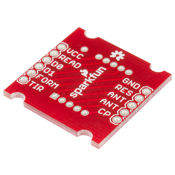
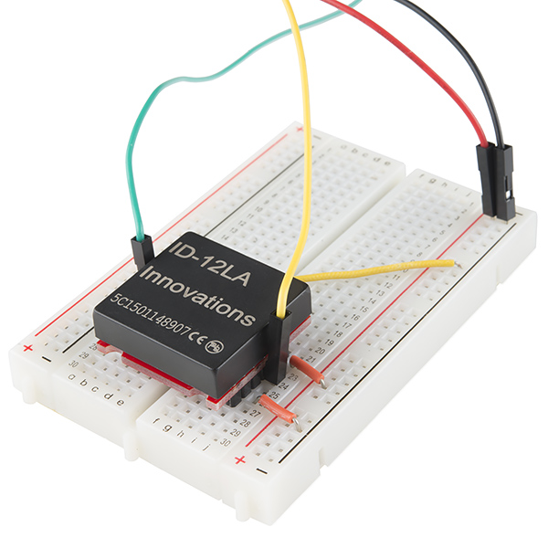
This is a simple breakout board for our RFID readers. The SparkFun RFID Reader Breakout converts the 2mm pins to bread board friendly 0.1" headers. With this ability the ID-3LA, ID-12LA, and the ID-20LA you can solder the reader directly to the breakout board or use the 2mm sockets.
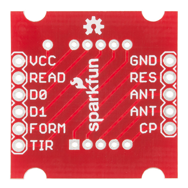
This breakout board's edges actually fit flush within the under side the ID-12LA. The board also works with the ID-20LA, but is smaller than the edges. As stated before each pin of the RFID reader has been broken out including: VCC, READ, D0, D1, FORM, TIR, CP, both ANTs, RES, and GND. We've even added four half-mounting holes to the board to easily secure your project!
Note: If you are concerned about soldering this board directly to the RFID reader, you can use 2mm sockets instead. This is due to the RFID being sensitive to heat and should be handled with care or if you would like to switch the readers out as you please.
- Schematic
- Eagle Files
- Using the RFID Reader Breakout
- GitHub (Design Files)
- Product Video
SparkFun RFID Reader Breakout Product Help and Resources
SparkFun RFID Starter Kit Hookup Guide
May 5, 2015
Learn the basics of how to get started with the SparkFun RFID Starter Kit.
RFID Basics
February 23, 2017
Dive into the basics of Radio Frequency Identification (RFID) technology.
Hookup diagram and test sketch for the RFID Reader Breakout
Need to test your reader with an Arduino? Use the hookup diagram and sample code you can find here to do so!
Core Skill: Soldering
This skill defines how difficult the soldering is on a particular product. It might be a couple simple solder joints, or require special reflow tools.
Skill Level: Noob - Some basic soldering is required, but it is limited to a just a few pins, basic through-hole soldering, and couple (if any) polarized components. A basic soldering iron is all you should need.
See all skill levels
Comments
Looking for answers to technical questions?
We welcome your comments and suggestions below. However, if you are looking for solutions to technical questions please see our Technical Assistance page.
Customer Reviews
5 out of 5
Based on 1 ratings:
1 of 1 found this helpful:
really helpful
make sure to get the the 2mm sockets and some 0.1" headers with it. The socket soldering is pretty tight, and I made sure to follow some tips from that product page to punch the pins through parchment paper and into the holes before soldering in order to prevent solder from flowing into and clogging the sockets.
I cut my headers and sockets using small side cutters, for the sockets just make your cut in the middle of the next socket. you can pull out the pin between vcc and read using pliers.
i'm working on designing a solder on board with space for LED's and a rj45 jack to connect back to an arduino. I'll post eagle files for that, when it's done.
Folks, do you sell 2mm pins to solder to these (weird) sockets?
We typically cut and use these.
Thanks.