- Home
- SparkFun AVR Programming Adapter

SparkFun AVR Programming Adapter
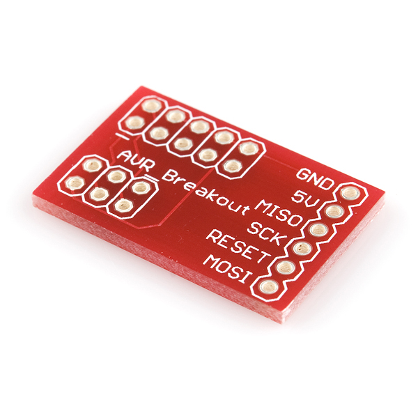
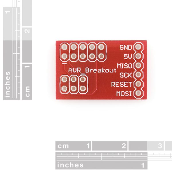
This is a simple, but extremely handy board to adapt the common 10-pin ISP programmers to the smaller 6-pin ISP connections. We also designed in a 6-pin inline connector so that you can insert this board directly into a breadboard! Good for the AVR programming tutorials. Pin 1 indicators indicate how the AVR-PG1 and PG2 should be oriented.
Board comes bare. We recommend ordering male pins to insert into the programmer and female pins to couple to the ISP connector on your target.
- Schematic
- Eagle Files
- GitHub (Design Files)
SparkFun AVR Programming Adapter Product Help and Resources
Core Skill: Soldering
This skill defines how difficult the soldering is on a particular product. It might be a couple simple solder joints, or require special reflow tools.
Skill Level: Noob - Some basic soldering is required, but it is limited to a just a few pins, basic through-hole soldering, and couple (if any) polarized components. A basic soldering iron is all you should need.
See all skill levels
Comments
Looking for answers to technical questions?
We welcome your comments and suggestions below. However, if you are looking for solutions to technical questions please see our Technical Assistance page.
Customer Reviews
4 out of 5
Based on 1 ratings:
Does the job
Does exactly what it should do.
That said, it would be nice if the 6 and 10 pin headers were oriented the same way (pin 1 towards the same corner of the board) instead of rotated 180 degrees as they are now. Would also be nice if they were mounted on a .1" grid so you could shove the two headers into a breadboard to hold them while you soldered them.
But it works.
@Sparkfun:
Nice adapter, but may I suggest an improvement concerning the inline connector?
Every AVR I have seen so far (at least the ones in DIP packages) have the MOSI signal at pin x, MISO at pin x+1 and SCK at pin x+2. If the adapter would have these signal in the same order, wiring the prototype on the breadboard would be easier.
And if you put VCC at pin x+3 you could connect most of the 8-pin ATTINYs with just 2 wires.
Some other suggestions for your next batch of PCBs, in addition to the excellent suggestion from Praetorian:
- put the "1" on the "outside", so it's easier to see it (i.e. not between the two connectors). Rotate 90 degrees from their pin 1 corner.
- don't put the "1" so close to the connector (especially the 6-pin one, see photo above)
- use a serif font so that's easy to recognize it's a "1" and not just a silkscreen glitch
Perhaps a better pinout for this would have been
Mosi,Miso,Sck,Reset,Vcc,GndThis pinout would make the adapter directly compatible with chips such as the Atmega644.
There would have to be some standard orientation of 1x6 pins to say that they "got it all wrong". I have seen several different pinouts and it really depends on what you are connecting. Now, there may be better pinouts than the one they use...
You're right, that comment was terribly worded. I have reworded it.
for use in bread-boarding I found putting right angle connectors in the 6-pin inline connector very helpful. that way it sticks straight up and doesn't use a lot of bread board space.
Would the shrouded headers (http://www.sparkfun.com/products/10877 & http://www.sparkfun.com/products/8506) fit on this board together?
That is what I was planning on using since they are in related products, but no clue if they would actually work. I don't see why not.
What? No Eagle files?
These are really nice. You can't, however, install two shrouded side-by-side for the 2x5 and 2x3 pin groups. The pin groups are spaced so closely together, with the pin 1 sides facing each other so closely, that you'll probably damage the ribbon cable trying to insert one cable or another into the plastic shroud. a 2x3 shroud plus bare male header pins for the 2x5 connector seem to work fine though. Just be careful of your pin 1 placement.
This is pretty nice. It works for me. I do wish that the pin 1 mark on the top of the board were easier to see, and also if there were a small LED built into it (with a switch to turn the thing on or off) so that we can rapidly determine if the ICSP connector is able to power the target project.
would both the 2x3 and 2x5 shrouded headers fit on the same board? If not I may just use the 2x3...
Soldered and working, now if it only came with header pins.
not as good as simular part found at www.kooing.com. The cost of this PCB and needed parts are the same.
Trying to understand the orientation of the connectors is not very clear for begginers =(
Some soldering example maybe?
There are a couple of pictures using this connector here How To Program an AVR Chip With The AVRISP mkII
Can't upvote this comment enough. Excellent example on this link.
Perhaps a pinout that would make it compatible with FTDI bitbanging (see http://doswa.com/blog/2010/08/24/avrdude-5-10-with-ftdi-bitbang) would be nice. That way, it would be very easy to program AVR devices from FTDI devices.
Note: this article is specific to Linux, but FTDI bitbang mode works with Mac OS X and Windows as well.
Will this work with 40-pin atmega's using jtag?
Nice board, but the 6 pin header isn't listed under related products. In fact, I can't find the 6 pin header at all.
Unfortunately we don't sell the 3x2 connector, however you are able to cut the 5x2 down to 3x2.
I find it easier to cut a 6x1 connector in two. If you hold it properly you can easily snap it with your fingers.
Now that I have been through the Embedded Electronis tutorials, I want to do my programming via USB from now on. Can someone tell me if this is compatible with the Pocket AVR Programmer (http://www.sparkfun.com/commerce/product_info.php?products_id=9231) or would I have to adapt it using the ICSP Adapter (http://www.sparkfun.com/commerce/product_info.php?products_id=9046)?
The cable in the 2nd pic appears to be plugged in backwards.
There is no cable in any of the pictures.
Not two years later there isn't.
How about soldering in the headers and pins for those of us with poor eyesight and shaky hands.
Checkout related item #DEV-09046 - the form factor is a little different, but looked to me like it might do what you need with less assembly required.
These are very useful if you use AVR's