- Home
- ProtoBoard - Koala (USB+PTH)

ProtoBoard - Koala (USB+PTH)
Replacement:PRT-10614. We've revised this board, adding a new charging circuit featuring the MCP73831 and correcting some footprint issues. This page is for reference only.
We asked ourselves what we would want in a project board. What would an ideal platform for most any given project look like? After putting a laundry list together of 'wants' and 'needs', we created the SparkFun Protoboards. We hope you like it as much as we do.
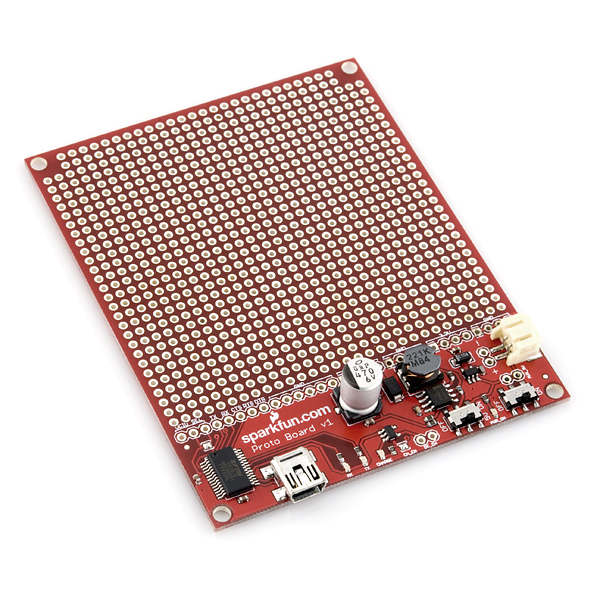
The marsupial naming convention is what happens when you let Engineers into a Marketing meeting. They looked so happy, we just couldn't tell them no. Koala is the board with USB serial, charging, and PTH proto.
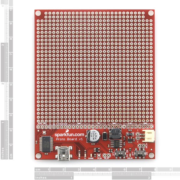
This is a project board specially designed to fit the Sparkfun Enclosures. The board provides the user with 3.3V and 5V regulated rails from a single Lithium Polymer battery. USB serial communication is also on-board with an FTDI FT232 USB chip, with selectable 3.3V or 5V logic. Many of the serial pins of the FT232RL, including RTS, are broken out. Finally, the board has a generous prototyping area for through-hole components (2.54mm, 100mil spaced holes).
The LiPo cell plugs into the provided JST connector, and charging is available over USB (100mA) or external source (5V, 250mA).
Note: This board was primarily designed to be used with a lithium polymer battery, the voltage output is only stable at 5 volts when the battery is connected. If a battery is not connected the board voltage bypasses the regulator and can be as high as 6.5V.
- 3.3V@100mA
- 5V@265mA (DC-DC Step Up)
- LiPo Battery Connection (3.8V nominal)
- USB-Serial TTL connection
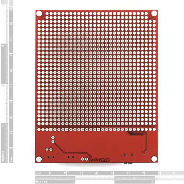
- Proto Area for PTH
- Fits SparkFun enclosure
Comments
Looking for answers to technical questions?
We welcome your comments and suggestions below. However, if you are looking for solutions to technical questions please see our Technical Assistance page.
Customer Reviews
No reviews yet.
This is a fantastic board. I just got it today, and I love it already.
One suggestion: Bring out the DTR pin for us Arduino users.
I bought this board last week, when it finally came time to move my project from a breadboard to something more permanent. It's working out pretty well, except I really don't like the tricks I'm pulling to bridge holes. I either make the stripped ends of my wire extra long so I can fold it flat on the bottom to the next hole, or just lay bits of wire on the bottom and solder them down. YUCK.
I'd love to see this with either breadboard-style wiring (all columns connected, split down the middle, plus rows all the way across for power and ground), or this style wiring (every hole connected on both sides, with easily-cut traces).
That's pretty much how pad-per-hole protoboards work. I don't think SparkFun sells wiring pencils (http://en.wikipedia.org/wiki/Wiring_pencil), but something like a Verowire pen works well for me for digital and low-current analog wiring. Discrete components are tack-soldered into the holes with a "solder tail", and I use the wiring pen to run a few turns around each desired pin/lead, then solder them down to make them permanent.
Would LOVE to see this using the MAX1874 instead of the MAX1555 -- Ability to switch to run directly of supplied power when available is great and opens up more options for not relying on LiPO.
So can we modify to wire the power from the mini-usb into the external charging port? This way we would get 250MA instead of just 100MA off the USB connection?
I'm using a 5v 1amp power source on the other end of the USB cable, and want to power off that single connection.
The datasheet for the MAX1555 makes the options clear here.
http://www.maxim-ic.com/datasheet/index.mvp/id/4002
In short, you can definitely trick the MAX1555 into charging at 280ma instead of 100ma, if you understand the potential impact on USB sources and the current they make available.
Any idea what "U4" 3.3V linear supply, 150mA in the schematic is? I am interested in the low battery behavior and LiPo undervoltage protection. Thanks
This would be extra cool if it would fit in the project cases like WIG-08601
it does.
Had this board for a month now, soldered up my circuit (which uses the 5v output and running from a battery). How scalding hot should the smt inductor get? Because mine is pretty darn hot, and noticeably "buzzy." How normal is this? Should I be worried that my handheld device with the attached LiPo battery might catch fire?
Features say "Fits SparkFun enclosure" which sparkfun enclosure?
This one.
Can you build one of these with the Atmega 8u on it?
Like this one:
http://www.sparkfun.com/products/10277
It would still do the serial, but make this board a lot more flexible.
Any plans to update the Koala with the TPS61200 boost converter being used on some of the newer boards?
Has this issue been confirmed yet? Im just about to buy some of these, and need 5v ouput to be working. Cheers.
I'm not sure it's an 'issue'. It could have been a single vagrant resistor that found its way into a suppliers tape. I've had stranger things happen.
At any rate, as usual, no hassles about getting a replacement from SF. Great company to deal with!
Be careful with this board... I had some issues with the +5 volt supply and found that one of the voltage programming resistors on the MC34063 was wrong (far too low as I recall). They're marked, so if you have good eyes or a magnifying glass you should be able to check the values (a DVM will work too). Since the assembly is automated I suspect there may be more boards with this problem out there.
What was wrong about it? Wrong value?
Yes... I returned it to SF, so there should be a record somewhere (Order #172996). The problem was a perfectly soldered but wrong value resister on the MC34063. I thought of this when I read Zom-B's note about +5v problems...
The new revised version of this board is fantastic. The dtr pin is broken out, and the inductor has been replaced with a different one. Thank you the old one was just too fragile.
So the DTR pin is available on the newest boards? Good to know! Thanks. Then the schematic needs to be updated to reflect this ;)
Would be handy to have each TH connected to one neighbor, so you can join leads/components more easily, instead of the "long wire" trick employed in a comment below.
Is my board faulty? I can't even draw 15mA from the 5V breakput pins.
I'm powering via USB, all switches on, and no lipo battery (not needed for what I want). I connect a cicuit that's supposed to draw 40mA at 5V and the 5V output drops to 2.8V and only 15mA flows.
Is this normal and do I need a lipo battery for more current or is there something wrong?
These marsupial boards are absolutely fantastic, but there's just not enough power there for me. I would pay like another $10 if it meant i could draw more than 500mA out of the 3.3V line.
I'm pretty happy with this board, but I'm a bit confused why when I measure the voltage rating on the 5V breakout pins I actually get 6.3v? (I get a clean 3.25v from the 3.3 pins for reference sake, and when I place the probe directly on the first pin of the USB plug and GND I get a normal 4.85v). Any idea why? I'm a bit afraid to use this to supply 5V power now, since 6.3v is probably above the maximum value for some components!
I read that if there's no battery connected the voltage can run as high as 6.3v.
IMPORTANT: Arduino Users:
To use this board along with the FTDI IC (F232RL) as an 'Arduino', you must connect 'DTR' (Pin 2) on the F232RL to a 0.1uf nonpolarized capacitor that then connects to the RESET line (Pin 1 on the ATmega8/168) so that the Arduino software (must be > version 8, and the ATmega must have the 'new' bootloader that allows software reset) can reset the AVR micro.
Unfortunately, as NickH pointed out, the DTR line is not brought out (HINT HINT Sparkfun...), so be CAREFUL when soldering to the DTR pin; try not to short other connections. It is kinda tricky to say the least; you're gonna need a steady hand and some serious skill to get that soldered (it took me like 5 tries!).
Perhaps I should note this in the forums, because if someone comes across the same issue, it takes forever to figure out the solution; it took me for EVER to figure out why it wasn't working! After looking at FTDI USB-SERIAL datasheets, arduino schematics, forum topics and such, I finally got it lol.
P.S. I did not need to bother with the VCIO jumper/solder short pad.
What kind of USB port is this exactly? Mini-A, or Mini-B?
I got this board a few days ago and it is really great with the exception of the DTR pin not being brought out. 99% of the microcontrollers I use need to have this for programming. Now, I am hacking out the DTR to a header so I can use it:) Maybe you nice folks at SFE can bring it out in the next revision.
To use an arduino on this board do i have to desolder the vcio jumper so it can use 5 volt logic?
If its a 5v Arduino board, yes it's best to unsolder the vcio jumper. 3.3v Arduino boards don't need that mod.
However, I've heard (but not personally confirmed) that the FTDI FT232 is robust enough to communicate with 5v serial devices even if its running at 3.3v.
Adafruit says that is true as well
What a nice board and a clever amount of always needed electronics, if you need serial port and batteries.