- Home
- ProtoBoard - Diprotodon (USB+Mix)

ProtoBoard - Diprotodon (USB+Mix)
Replacement:PRT-10620. The new version of this board makes some minor hardware changes including an update to the charging circuit which now uses the MCP7381. Other than that it's the same board you know and love. This page is for reference only.
We asked ourselves what we would want in a project board. What would an ideal platform for most any given project look like? After putting a laundry list together of 'wants' and 'needs', we created the SparkFun Protoboards. We hope you like it as much as we do.
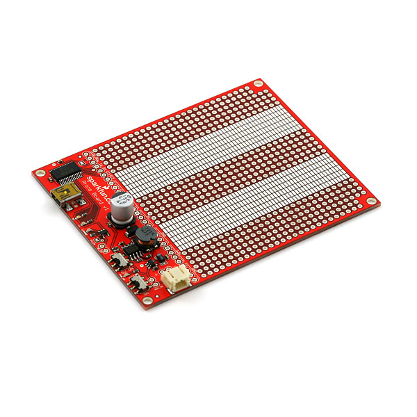
The marsupial naming convention is what happens when you let Engineers into a Marketing meeting. They looked so happy, we just couldn't tell them no. Diprotodon is the board with USB serial, charging, SMD proto, and PTH proto.
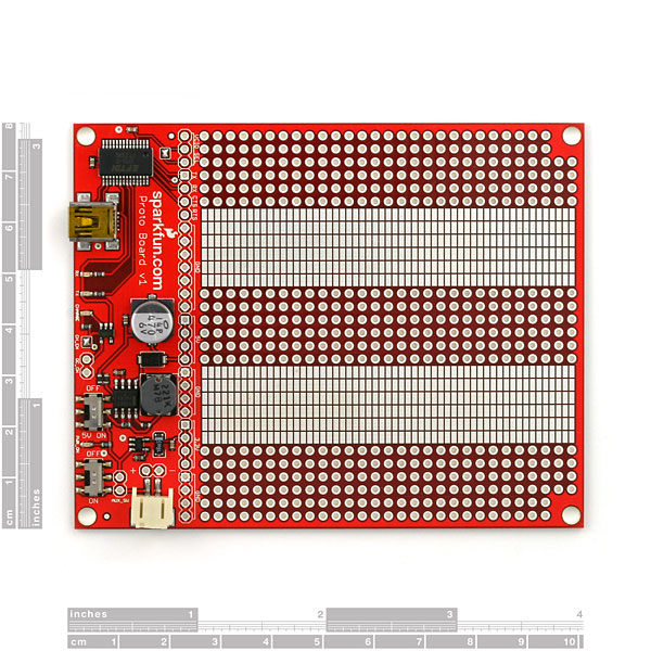
This is a project board specially designed to fit the Sparkfun Enclosures. The board provides the user with 3.3V and 5V regulated rails from a single Lithium Polymer battery. USB serial communication is also on-board with an FTDI FT232 USB chip, with selectable 3.3V or 5V logic. The LiPo cell plugs into the provided JST connector, and charging is available over USB (100mA) or external source (5V, 250mA). Finally, the board has a generous prototyping area that allows a combination of surface mount (2.54mm x 1.27mm, 50mil x 100mil pads) and through-hole components (2.54mm, 100mil spaced holes).
- 3.3V@100mA
- 5V@265mA (DC-DC Step Up)
- LiPo Battery Connection (3.8V nominal)
- USB-Serial TTL connection
- Proto Area for SMD and PTH
- Fits SparkFun enclosure
Comments
Looking for answers to technical questions?
We welcome your comments and suggestions below. However, if you are looking for solutions to technical questions please see our Technical Assistance page.
Customer Reviews
No reviews yet.
Thanks for putting the ascii version of this up - the detail is amazing and since it is text I can clearly determine the circuit paths.
Definitely need to link the pads to the holes, then you could just use the female-to-female jumpers and molex pins to quickly wire up the circuit...
+1 for SMD --> PTH connections.
This board is great!
It would be very useful, though, if the rows of PTH holes adjacent to the SMD pads (at least on one side) were connected. This would make interfacing to off board resources with standard pin headers or wire wrap much easier.
-- Dave
The Lab wags his tail for this idea!!!
This line:
Also in FIG 4 of the instructions the #4 points to CH_EN, but it is supposedly pointing to CH_EN.
should be:
Also in FIG 4 of the instructions the #4 points to DC_ON, but it is supposedly pointing to CH_EN.
Sorry for the confusion.
There are inconsistencies with the schematic designations SJx and the documentation designations of VCIO Select and CH_EN.
The DC_ON pads don't seem to be listed in the schematic or datasheet and the #4 points to it erroneously for CH_EN. The arrow should be to the left about 1/4".
The sense of CH_EN is different for the schematic and the shipped version. If the instructions say it should be removed then so should the schematic, but the instructions say remove and the schematic says install for opposite correct functionality and thus if you look at the schematic you think the default is removed, but when you read the instructions, the default is installed.
I'm very confused.
There are pads labeled CH_EN and DC_ON BUT they don't exist as those designations in the schematic.
Also in FIG 4 of the instructions the #4 points to CH_EN, but it is supposedly pointing to CH_EN.
Why should the schematic say "Close to Enable Battery Charging" and here they are Talking about SJ1. Isn't SJ1 closed when shipped? Isn't SJ1 really CH_EN?
Where/what does SJ2 in the schematic do? Where is it on the PCB? SJ2 is I guess VCIO select and is described in #6.
Question still remains what is DC_ON and why does #4 in Fig 4 point to it?
I ordered this board and I hope some of my difficulties will become more clearer when I get it.
The documentation doesn't map component designations to the silk screen.
I think the data sheet should mention the prototype area and the overall dimensions although it's in the detailed drawing.
The info for VCIO select really doesn't tell you what the position is for in or out. I think I get it, though.
4.The p.n of U4 isn't listed in the schematic, but the p/n's of all of the other parts are. Is this a 3.3 shunt regulator?
Would have been even better with a LDS3985M33R regulator which would output 3.3v @ 300mA since thats a more realistic amount of current people use...
They only cost about $1 each. Expensive a bit but im sure you can buy in bulk.. not sure how much a difference the total cost would be but still would be better...
If anything i think it can be used as a drop in replacement people so if you need more power just buy one of those and replace it.. (if you have the soldering skills)
I was wondering if the board automatically charged the battery when USB is plugged in? and than if the USB cable is un-plugged if the board automatically switches back to the battery for power?
If you look at the schematic, it looks like if you close SJ1 it charges the battery
If I wanted to measure the battery level - is it as simple as connecting the + to an analog IO pin on my arduino?
(The + being the one right in front of the battery connector.
I would like to duplicate the functionality of this board into my own circuit. What chip is used to create the 3.3v source from the lithium battery, and do you sell this chip?
i am trying to connect this protoboard with the RBBB using the mini USB.
i have the tx, rx and ground connected from the protoboard to the RBBB correctly.
is there anything on the protoboard to connect the RBBB's reset pin? CTS or RTS?