- Home
- Product Categories
- Modules
- GPS Receiver - LS20031 5Hz (66 Channel)

GPS Receiver - LS20031 5Hz (66 Channel)
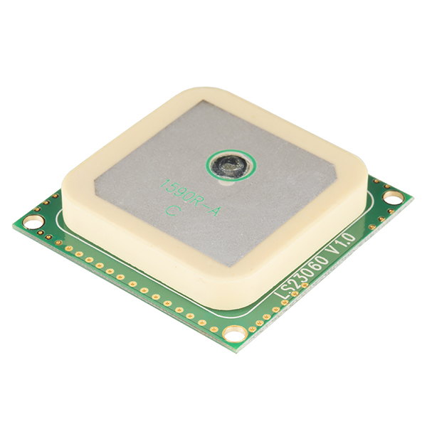
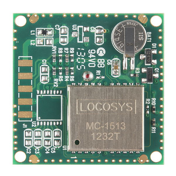
The LS20031 GPS receiver is a complete GPS smart antenna receiver, that includes an embedded antenna and GPS receiver circuits. This low-cost unit outputs an astounding amount of position information 5 times a second. The receiver is based on the proven technology found in LOCOSYS 66 channel GPS SMD type receivers that use MediaTek chip solution.
The GPS smart antenna will track up to 66 satellites at a time while providing fast time-to-first-fix, one-second navigation update and low power consumption. It can provide you with superior sensitivity and performace even in urban canyon and dense foliage environments. The capabilities meet the sensitivity requirements of car navigation as a well as other location-based applications.
Not sure which GPS module is right for you? Check out our GPS Buying Guide!
Note: The datasheet for this unit states that the update rate is configurable up to 10Hz but we've found that it is most reliable at the default rate of 5Hz.
Note: The new version of this module uses the MT3339 MTK chipset.
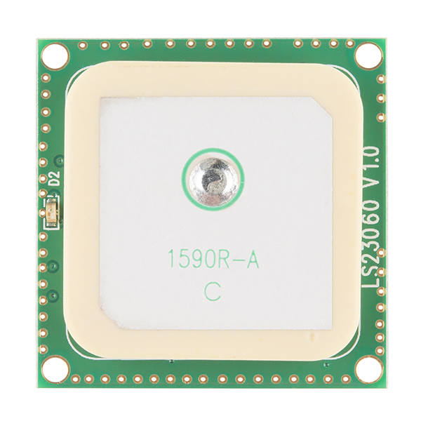
Note: Unit does not contain a connector, however there are 5 bare pads you can solder to. Check out our tutorial on how to solder a right-angle 5-pin header to the pads. It's easier than you might think.
Note: Hacking makes the world go 'round, but be careful if you decide to flash some 3rd party firmware to this module because we cannot get the original for you. If 3rd party firmware breaks your device, according to the manufacturer, you're on your own!
- MediaTek MT3339 solution
- 5Hz output
- 57600bps TTL serial interface
- 3.3V @ 41mA
- 66 Channel GPS
- Fast TTFF at low signal level
- Up to 10Hz update rate
- Capable of SBAS (WAAS, EGNOS, MSAS)
- Built-in micro battery to preserve system data for rapid satellite acquisition
- LED indicator for fix or no fix
- Datasheet
- PMTK Protocol Reference
- Great configuration software: Mini GPS
- Example Configuration from DIYDrones
- Connection Tutorial
GPS Receiver - LS20031 5Hz (66 Channel) Product Help and Resources
LS20031 5Hz (66 Channel) GPS Receiver Hookup Guide
December 13, 2018
In this tutorial, we will solder headers to the surface mount pads of the LS20031 GPS receiver and read the output using an Arduino!
Alphanumeric GPS Wall Clock
January 26, 2015
This is a GPS controlled clock - a clock you truly never have to set! Using GPS and some formulas, we figure out what day of the week and if we are in or out of daylight savings time.
GPS Basics
December 14, 2012
The Global Positioning System (GPS) is an engineering marvel that we all have access to for a relatively low cost and no subscription fee. With the correct hardware and minimal effort, you can determine your position and time almost anywhere on the globe.
Satellite Fix Issues
If the GPS holds on to bad almanac data and will refuse to get a fix even though plenty of satellites are in view. The solution is as follows:
Open a serial port on the GPS at 4800, make sure you're sending a CF & LF.
Send the command
$PMTK104*37(which corresponds to FULL_COLD_START in the manual ) as ASCII.
Core Skill: Soldering
This skill defines how difficult the soldering is on a particular product. It might be a couple simple solder joints, or require special reflow tools.
Skill Level: Competent - You will encounter surface mount components and basic SMD soldering techniques are required.
See all skill levels
Core Skill: Programming
If a board needs code or communicates somehow, you're going to need to know how to program or interface with it. The programming skill is all about communication and code.
Skill Level: Rookie - You will need a better fundamental understand of what code is, and how it works. You will be using beginner-level software and development tools like Arduino. You will be dealing directly with code, but numerous examples and libraries are available. Sensors or shields will communicate with serial or TTL.
See all skill levels
Core Skill: Electrical Prototyping
If it requires power, you need to know how much, what all the pins do, and how to hook it up. You may need to reference datasheets, schematics, and know the ins and outs of electronics.
Skill Level: Competent - You will be required to reference a datasheet or schematic to know how to use a component. Your knowledge of a datasheet will only require basic features like power requirements, pinouts, or communications type. Also, you may need a power supply that?s greater than 12V or more than 1A worth of current.
See all skill levels
Comments
Looking for answers to technical questions?
We welcome your comments and suggestions below. However, if you are looking for solutions to technical questions please see our Technical Assistance page.
Customer Reviews
4.5 out of 5
Based on 2 ratings:
1 of 1 found this helpful:
Work's well
The Module has good sensitivity. It is configurable by text sentences. But does not tolerate 5V on it's data inputs. Doing so will kill the Chip. I've accidentally done this a couple of times during R&D and bought new replacement modules.
Good
Good
hello, this module is currently working ? there is no issue with the April 6th weekno rollover ?
Just tried one and they work OK. Giving the correct position fix and date/time.
Insert Skethup 3D model, at least!
I purchased 2 of these GPS units for a class QuadCopter project. We've learned the following along the way:
If you're using a 5V arduino (Uno, etc.), you can only receive data from the GPS, but you cannot send commands as you risk frying the GPS. If you're using a 3.3V arduino (Fio, Due, etc.) you can send commands to the GPS from within your programs, including the hot start command. The code below will send the hot start command to the GPS (Note: use println so the required <CR><LF> is automatically appended at the end of the command.)
gpsSerPort.println("$PMTK101*32"); //hot start GPS
Software serial on our Uno board could not keep up with the default 57600 baud rate. We used MiniGPS to turn off all sentences except GGA and RMC, to reduce the update frequency to 1Hz and to reduce the GPS baud rate to 9600. With those settings we were able to get software serial to work.
Your information was a great deal of help. What an amazing GPS. I happened to have an FTDI EZ Flex Adapter (3.3/5v Jumper) and followed the instructions for LS20031 GPS Assembly Guide here on SparkFun. With MiniGPS I can query and set the parameters-it works perfectly. For just viewing the data VisualGPS (now free) works too. This post really set me on a path to getting it working. Thanks.
The pads on back are 0.1" spaced, and 2 of the pads are redundant GND, only 1 needs connection. Conveniently you can solder a 4 position strip of 0.1" header pins to it. You can also simply strip ends of wire and solder them direct. Very easy with 0.1" spacing.
With SAW filter, LED status, built in RAM backup super cap, and slight lower mass, and same command set as EB-85A, this unit is by far my preferred choice over the ETek unit.
If you make a serial connection to your PC, you can use the same media Tek PC programs that Saprkfun has on the page for the EB-85A (Mini GPS, GPS locator utility.)
Thanks Dean,
I soldered the wires directly to the pads.
everything works great.
Alex
Hello,
What is the input voltage range? please
Thanks
Page 10 of datasheet. LS20031: 3V to 4.2V(max) 3.3V typical. I'll post to description as well.
Anyone know how accurate this is?
It's accurate withing 1-2 meters
Check the datasheet
i got an output from ls20031 GPS i checked it using google map but it shows 2-3km away location please help me...
The datasheet does not mention SiRF Binary mode at all, does this module support it?
How does this compare to the FV-M8 you carry? That's a big price difference.
This module is on par with FV-M8 (formerly the EB-85A) module in terms of protocol, sensitivity (tested both modules indoors in the basement) and functionality (minus a second UART RX/TX pins of which wasn't useful on the EB-85A anyway).
The two really nice features that this GPS module has, compared to the FV-M8, is a battery to preserve GPS data and quite a bright red LED that blinks once per second upon fix. Not to mention the big price difference.
It is more convenient to use without requiring a special cable and connector (or a break out board) as others have mentioned about it. Overall I see it as a great replacement/alternative for the FV-M8.
Now there is one interesting difference from this module and the FV-M8 is that there is no EMI shield housing the components. Not sure if that will effect or matter to anybody else in terms of quality of the module because so far I've seen nothing wrong with the LS20031 module.
Ok, What is the most accurate GPS you sell Sparkfun?
The L1 (see top-left of PCB) burned up on the unit that I have. Would anyone know of a replacement part that I could use to repair the PCB?
Anyone know how much this weighs? That info would be greatly appreciated.
I know the datasheet says that it can operate beneath 50 km, but does it though? Even with the 18 km limit set by the US? The US limits also state that it can't operate if the device reaches a speed more that 515 m/s but maybe they mean that it can't operate if both of these limits are reached?
Does anybody know?
Highly recommend this gps. got it tracking on google earth via xbees and uno's so easily. the position on the map is the exact part of my house the gps is in, so it looks real accurate. picking up signal indoors no problem.
I Doubt it is normal, but my GPS is showing itself being about 20 Km South and about 1 Km to the right of my actual position
is there nothing you can just get and it "works" like it is suppose to?
Hi Sparkfun !
do you have any simple example of shemactics where we could power up this gps with one transistor and a microcontroller? or something like that?
i bought this one two years ago. it work very well, but i m looking for a perfect start up from a µC !
thanks !!
How does a 66 channel GPS help you when there are only 31 GPS satellites?
It has to do with the speed of the first fix. Identifying the presence of a GPS satellite (and identifying which satellite that is) is a complex operation that requires trying a lot of combinations and seeing which one works. The more receivers that can do this in parallel, the faster the satellites will be identified, and the faster it will arrive at an initial navigation solution.
hi .... i brought one of this gps. but the model number is LS23060 v1.0, i couldn't find it in the datasheet. im not sure what is the module it uses, can anyone help me?
Quite interested in this project for a marine application. Newly addicted to hacking so would love any help offered! I need to design GPS GPS device which will send GPS coordinates to a mobile Sat phone. Since locations will be quite remote and vary I need to be able to change th mobile number SMS will be sent too. Need one-way communication (GPS coordinates via SMS to mobile number or Google EArth) OR could go with two-way where coordinates are sent to mobile once the mobile sends out a request via SMS. Could the 66 channel 5Hz receiver work?
Thanks!
I've just been messing with this thing and having a lot of fun. But I first realized I was not getting any speed data(TinyGPS). I looked into it further and found that I only ever receive GPGGA but never have I seen GPRMC. TinyGPS only sends out speed when you have a $GPRMC signal. Are there settings I'm not seeing?
I fixed it... Found that it was sending the info faster than the arduino could read, so it was skipping over the $GPRMC. This is what I changed:
In NewSoftSerial.h: NewSS_MAX_RX_BUFF 64 to NewSS_MAX_RX_BUFF 256
Now it works perfectly. Will this cause any issues?
I'm looking for a simple script for Arduino to read in the NMEA sentences from this GPS and save them to an SD card. (probably need to store the data in a string or other variable and then copy them to the SD card)
Does anyone have any suggestions on where I can find anything like this? I've found a lot of info on decoding the NMEA but I want to leave it untouched and just save it exactly how it's coming of the GPS unit.
Thanks
Can anyone help me here? Im trying to write a simple arduino sketch that will read in the NMEA sentences and write them straight back to an SD card using this GPS unit. Does anyone know of any examples that read the NMEA sentences straight through with none of the extra decoding parts?
Thanks
Hello, Can you put a 3DR Telemetry between this GPS and an arduino serving as ground station? (RX - TX from GPS to 3DR transmitter, RX - TX from 3DR receiver to arduino?)
When I connect my LS20031 GPS 5Hz reciver to Arduino Mega 2560. It does not get a lock. LED keeps on blinking(its like turned on) without an Interval of 1 sec. Does this GPS unit need to be located outdoors? How much time does it take to acquire cordinates with clear sky?
it sounds like a power supply problem--too much power, board constantly resets, too little power, sensors draw power and cause board to reset. Try checking the power.
If the GPS is blinking, that means you have a lock--I'm getting a lock from my mega but I'm not outputting any real data from the GPS.....it works on my Uno but not the Mega for me...
You should be able to get a lock outside with clear skies in a few minutes at most. Make sure everything is powered correctly and wired up correctly, but if you are still running into problems, contact us at techsupport at sparkfun dot com and we can help you out.
Just a warning for anyone who tries soldering to the bare pads, try avoiding using individual right angle headers rather than the bundle of five. I order a bundle of six, and when I tried breaking one off, another came with it. The single one which was soldered to the second ground pin broke right off of the board, solder and all.....leaving me with one less ground--but still functional!!! Please be careful!!
If someone could help, do the tx pins on the GPS go to the rx on the Arduino? Some examples show the tx and rx pin being switched, maybe to show which pin it goes to on the Arduino; I'm not quite sure... Can someone tell me what goes to what please?
Check out the connection tutorial linked above.
Is there a compass built in to the GPS?
I'm trying to be able to get a sense of direction without using a triangle equation to find orientation
Very nice GPS! I`m also received an LS23060 instead of LS20031, but pinout is the same. My Vcc is 3.3v, boundrate 57600-N-8. In my house I got 13 satellites in view, which is really nice, my old one with external antenna can reach only one....
Someone may found useful this links:
http://home.online.no/~sigurdhu/index.htm - Some information to how to calculate coordinates, etc...
http://aprs.gids.nl/nmea/ - NMEA sentences
I got the same one too. Where you having and problems with obtaining data after locking the satelites? I'm trying to debug what's wrong but can't seem to pinpoint it. I'm using the tinyGPS examples.
For PCB mounting does this need to have all ground planes eliminated under it? Is it OK to route signals or planes under this unit?
I was soldering connectors to this, and the shield popped off. Will it still work or do I need a new one?
Quick question: I notice the red led will sometimes get stuck solid on with no output from the unit. The data sheet doesn't address this LED mode. Does anyone know specifically what this "solid on" led state is indicating?
I also have this question did you find an answer for it? Um using Arduino Mega 2560 to connect the GPS device.
how did you connect the GPS to the Mega? I can't seem to get it working on my Mega.......only my uno works with it...
Anyone have the NEMA_Parser.rar file (or its contents)?
Thanks!
KM6VV
I can't manage to receive any ascii data from the module, all that it outputs are strange values as can be seen on the image here: http://dl.dropbox.com/u/46462264/LS20031%20Output.PNG
As you can see from the image, I set the baudrate to 57600 8N1 which should be the default setting, but I have also tried all other settings without any improvement. I have already reset the GPS by shorting the battery for a few seconds, but it didn't help.
Any idea or help? thanks a lot!
Problem solved :-)
I was using the GPS module together with the RN-41 Bluetooth module and I only changed the baudrate of the link between the PC and the bluetooth module. But it was the baudrate of the link between the bluetooth module and the GPS module that was wrong..
I'm confused, in the description you say it is 5Hz, but other places 10Hz. Which is it?
Sorry about that. We have a lot of data to parse through, and some times things get screwy. I am looking into this right now, and we will get things straightened out. Thanks
This is an extremely nice GPS receiver! Its very sensitive. I have a to story home. It didn't get much of anything int he basement but on the first floor its getting 8 birds with good SNR. When it has that many birds with good signal, VisualGPS reports error < 1 foot in all directions for several minutes. Can't wait to try it outside (its a little chilly tonight).
So far the only downside is the lack of a comprehensive command reference. There is a PDF with a bunch of commands but it is missing some important ones. like how to change the baud rate. It does tell you how to turn certain NMEA 0183 sentences on and off though. By googling around I think all the commands are available.
Perhaps before the sailing season is over here int he Northeast I'll get this on my boat. I probably have about 1 week left!
I'm having some issues with this GPS. Sometimes, when powered on, it just sits there with the red LED on and doesn't spit out any messages. This seems to be intermittent. Other times, it comes up instantly and starts spitting out messages that I can read from the UART interface.
Any ideas?
OK - so the problem seemed to be related to my power supply circuit not being able to provide enough juice on startup. The micro was being clocked at 16MHz. I downclocked the micro to 4MHz, and now it starts up reliably.
Um using Arduino Mega 2560. Do you know how to downclock the Crystal in it?
Good little device, i just wish that there were some definent information on being able to send commands to it.. going into my quad:photobucket link
I had the older SUP500F GPS module that I was using for a project, and just replaced it with this one...
The new one gets a signal so much faster and stronger, it's a world of difference. This new module is simply fantastic.
Great unit, easy to configure and fast/configurable output. My only complaint right now is that I can not for the life of me get an accurate lock-on to my location. My gps module is always about 30minutes off in its LAT/LON coordinates output. Has anyone else experienced this or know what the problem might be? (Of course I have tried the obvious, going outside and pointing it up into clear sky but this produced the same results).
I received my LS20031 yesterday and when hooked up it does nothing.
No fix (led) and outputs nothing.
Are there any checks I can perform to figure out if the hardware is bad?
What I've checked so far:
- I don't measure any voltage across the onboard battery. If the battery if faulty, not just dead, does this device still work? The block diagram is inconclusive.
- Voltage at the first component "L1" but nothing on the other side of it. Without a schematic, I'm not sure this is a bad thing...
Have you tried the connection example in the quickstart guide; http://www.sparkfun.com/tutorials/248 if not, give that a try. if that doesn't work, drop tech support an email and they can help you out.
I have tried both tutorials (http://www.sparkfun.com/tutorials/176, http://www.sparkfun.com/tutorials/248) and emailed tech support...no response.
I have been happy with this receiver, but now I have a problem. All of a sudden the chip has started to draw 250mA of current and it's getting somewhat hot. Has anyone else encountered this? What might cause this behavior?
I'm having issues using this with the tinyGPS. I am not getting valid data for date, course, and speed. It shows 0/0/2000 for date, 99999999 for course, and 99999999 for speed.
I'm getting 0 checksum errors. I don't know if anybody has solved this issue because it seems other people are getting this same error.
Thanks
Hey,
i got this a couple weeks ago, i've got it wired up just fine to my mbed and am receiving serial data, but it appears that all of the GPS fields are blank.
I.E. $GPRMC,014719.348,V,,,,,0.00,0.00,100411,,,N*40
I'm a bit of a novice when it comes to GPS, is there something i don't know about? I have the V+ to 3.3V and must have tx/rx correct because i wouldn't be receiving characters at all otherwise. does it matter if i'm in Canada? (possibly stupid question...?) is it possible I fried the gps receiver somehow?
you aren't getting a lock. contact techsupport@sparkfun.com and they can help you out.
Same problem here. I'm from Germany. I think it doesnt matter where you're from. Any solutions?
Bump
Is there any way how to put this module into some power-saving mode (with some special UART message)? Thank you for any answer.
you could possibly supply power to it with a pair of IO pins, and then bring the pins output low when you want it to turn off. Many micros can so 25mA per IO, so 2 IOs might work for that.
hi,just asking. can i use this device with OpenGTS?
Can this do SBAS/WAAS at 10Hz? I've seen many chipsets, but the only one that could do both was the Venus (and now there is a version that does 20Hz). Does it have AGPS support?
I've compiled a good bit of info about this GPS and posted it to the Dallas Makerspace wiki.
Any idea as to when this item will be available again? How long with the backorder take?
Hey, does anyone know how to send data to the GPS to get it to send Lat ad Long at 5hz using an arduino? I looked at the datasheet and fond what I have to send ($PMTK220,200*2C) but I have no idea how to send it, or what I should send it as (BYTE, DEC...) Thanks in advance for the answers!
Sam
MiniGPS v1.4 is the program to use or Arduino sketches.
Some info here: http://code.google.com/p/ardupilot/wiki/MediaTek
Yah, but using Arduino Sketches, how do you send the information to the GPS?
Sam
Figured it out....just use Serial.print($PMTK220,200*2C). That will print it in ASCII form, which is what the GPS reads.
Sam
My MTK 3329 GPS module has become unresponsive, outputs garbage and will not respond to ANY commands. Battery has been removed to allow reset - still nothing. Any suggestions?
You are probably on the wrong baud rate. Mine defaulted to 57600 8N1, so I suggest starting there.
ETA on getting this one back in stock? :)
I would absolutely love to see a GPS shield for this module!
Would just like today that these modules work perfectly, after the quick, pain-free configuration from DIY drones. I have two modules and they are both creepy accurate, the battery almost never fails me (except on extended no-use periods, like two months), and I can get 9 satellites sitting in my basement.
At the end of description there is this note:<br />
The new version of this module uses the MT3329 MTK chipset.<br />
<br />
Does this mean that this GPS can update now at 10Hz like is described on other sites for this chipset?
As of today, all new modules shipped will have the updated firmware.
I ordered this module after the ordering page said that the MT3329 chipset was available, but only recently figured out how to verify this with the PMTK_Q_RELEASE command. However, when I tried this, the response I got back includes the sub string "Mcore" which seems to indicate I have the older 3318 chipset. Can you confirm the correct response I should get back for the MT3329 chipset?
You will have to contact our tech support department for that, sorry. techsupport@sparkfun.com. They should be able to help you.
Depending on your country you can get the RTCM data over the internet (this is called virtual reference station VRS). In many regions of Spain you can get this data stream for free (in my case I get it for Catalonia over the ICC institute). If you haven?t such a service for you region or country you need a radio receiver for the EGNOS base stations (in Europe) but I haven?t tried this.
Remember that if you are going to use RTCM protocol data you must set the correct protocol with the PMTK_API_SET_DGPS_MODE, by default this is set to WAAS.
I hope that this will be useful for somebody.
I turned my LS20031 GPS module into a DGPS module.
To do this you just need access to the second serial port of the MC-1513 chip (I can?t understand why Locosys haven?t made a pad for this).
The MC-1513 chip is able to receive RTCM correction data over the ?B? serial port, so you need to solder a wire to the pin number 1 (RxB) from the MC-1513 chip and connect it to your microcontroller or what ever you are using.
You can use the module in DGPS mode using two serial ports:
- TxA: for receiving NMEA data
- RxA: for sending configurations (MTK protocol)
- RxB: for sending RTCM data
If you have only one serial port you can put a switch for selection of RxA and RxB (normally you configure you module only once and then you use it)
That?s a link for the MC-1513 datasheet: http://www.locosystech.com/download/module/MC-1513_datasheet_v1.0.pdf
I'm having a weird issue with this gps device. It is reporting back data to me continuously but the latitude and longitude are wrong. I tried it at my house and it was about 2 degrees off in longitude, and I'm here at my father's now (about 6 hours north) and the longitude and latitude are the same as when I was at my home, although the digits after the decimal are changing. The time it is reporting is accurate. I tried shorting out the battery but no change. I do not have a good signal as it is raining out so I hope that is the issue. I don't have the equipment necessary here to get any more data than the latitude,longitude,altitude and time and I can't configure the gps here anyways. Anybody have any ideas why it would do this? (By the way, I've used it before, a few months ago and it worked great).
Nevermind, it got a good signal with the weather clearing up and the position is correct now.
Has anyone used this with a PIC?
I have one of these and its working great. I also have a bluetooth module "Bluetooth Modem - BlueSMiRF Gold". By default it's configure for SPP (serial port protocol) service. I would like to pair this bluetooth up with this GPS and use them as a real time GPS-blueooth module. Does any1 know how to configure it so it appear to be a GPS-blueooth module to computers/handheld devices?
Please disregard my previous statement about longitude being ~0.9 degrees off... It turned out to be a simple error on my part when logging a double floating-point. Arduino doesn't implement "%f" in sprintf(), and my workaround was writing "xxx.9" where it should have been "xxx.09". Oops! The good news is that this GPS is pretty good and usable!
My observations:
- Board says LS23060 V1.0 on it, but it doesn't match the datasheet for that part (it obviously doesn't have the LS23060's USB connector, it samples at 5Hz not 4Hz, etc)
- Gets a decent fix even when indoors, and in less than ideal mounting locations in vehicles
- GPS fix is fast if it was recently powered up, but can take ~5 minutes (indoors) otherwise
- BAUD rate is 57600, not 9600
- Default sample rate is 5Hz, not 1Hz
- Sometimes the Longitude is off by a consistent ~0.9 degrees. It can do this even when it has 9+ satellites locked, as well as when in DGPS mode. I've seen it several times, and with standard and DGPS fixes. Looks like a steady error, so it may be correctable with software, but there's clearly something wrong here! Could be disaster for a UAV or similar use.
- Is "TTL" 3.3v or 5v? I'm powering it with 3.3v, but my comm is at the typical 5v. Seems to work, but makes me wonder if I'm going to mess something up. Do I need to add a voltage divider on its Rx pin or not?
- What happens when that little battery goes dead?
Good question. I found this out the hard way.
The battery appears to be a "batcap" (but I could be wrong - wouldn't be the first time! :-). It charges when there is power to the device and will hold a charge for a good long while with power off, maintaining the settings from software commands having been sent (like change the baud rate, 1hz update rate, etc...)
If the device is without power for a long time, it will reset to the default settings that have been programmed into the EEPROM. If the EEPROM has not been updated by software command, the default will be the factory settings.
I made the mistake of programming this GPS to accept a particular (slower) baud rate on one (faster) microcontoller, to use with another controller that had the slower maximum baud rate. A month went by and I had a hard time figuring out why the GPS wouldn't talk to the controller anymore - the batcap had died and the unit powered up with the faster default settings.
Lessons learned - I should know better!
Lesson 1 - Don't assume the (GPS) hardware will hold its settings unless they are put into EEPROM.
Lesson 2 - Don't get fancy with swapping hardware between projects.
Lesson 3 - Keep special setups a software thing - done each time the unit is powered up.
Regarding the FTDI cable to configure this module, do i need to get a 3.3v cable? As far as i could tell from the ardupilot config guide Vcc of the cable is ignored in replace of an external 3.3v source suggesting a 5v cable would work. Does mean the tx signal from a 5v cable is 3.3v or can the GPS module accept a 5v signal on the rx pin without damage?
Also just to confirm, the FTDI cable and rx pin of the module is only used to configure it. During operation I just connect the tx pin to the rx pin of an arduino directly? Finally, will the 3.3v supply from an arduino provide enough current to power this during peak load?
I want to solder a header onto this that will stick off the side like a few people have recommended. It looks like the pins that I solder to pads 4 and 5 may touch the little vias along the edge of the border. Does anyone know if those vias are connected to anything and if this will be a problem? Pins four and five are ground.
Thanks,
Dan
DanielBenamy: I want to solder a header onto this that will stick off the side like a few people have recommended. It looks like the pins that I solder to pads 4 and 5 may touch the little vias along the edge of the border. Does anyone know if those vias are connected to anything and if this will be a problem? Pins four and five are ground. Thanks, Dan
Those vias are GND. Or at least that's what I remember! use a multimeter to check for continuity there... Since pads 4 and 5 are ground I think that what you are planning should work
OK - I am having a heck of a time getting this connected so that RealTerm can see it.
I am using the TTL-232 USB cable here (http://www.ftdichip.com/Documents/DataSheets/Modules/DS_TTL-232R_CABLES_V201.pdf)
I wired it with:
GPS --> Cable
Pin1 - Red (VCC)
Pin2 - Yellow (RX)
Pin3 - Orange (TX)
Pin4 - Black (Gnd)
Pin5 - Black (Gnd)
I have tried the various baud speeds listed in these threads, but get no connection.
Any help/suggestions would be greatly appreciated!
Never mind... I RTFM (other posts) a little more closely...
What determines the rate at which the position measurements are made? The specs say 1Hz through 5 (probably 10 now)Hz. Is there any way to talk to the module to set baud rate, etc?
I'm a bit bummed today -I just bought this GPS and its already the old version. I just found the lastest and greatest LS20031 for the same price and it tracks 66 channels @ 10Hz. I thought I saw a post about a firmware update to 1.xx. Anyone got info about he update???
Yes, I got this working and it does get enough satellites to run INDOORS in the cavernous building I work in. I am very pleased.
Hello,
I ordered this product and received the LS23060. Is this product equivalent to the LS20031 regarding pin layout and communication with my Arduino?
The only datasheet with the same number I found is the one for the GPS mouse:
http://www.locosystech.com/download/receiver/LS2306x_datasheet_v1.0.pdf
Can you please publish one for the LS23060 module?
It looks to me like I have to connect my gps module to 5V instead of 3.3V, right?
After checking the datasheets for the other series it looks to me like the last digit in the device name stands for the communication channel (0=USB, 1=RX/TX). Is it possible to communicate with the LS23060 via the Arduino serial pins?
Thanks a lot in advance!
Best regards, Robert
I to recieved the LS23060 GPS instead of the LS20031 GPS 5Hz Receiver I ordered. I need the 3.3V TTL LS20031 GPS reciever I ordered. There is no documentation on the LS23060 and I have not been able to get it to work.
Has anyone been able to get the LS23060 gps to work with Arduino? Is it a 3.3V TTL reciever? Any help would be appreciated. Thanks Don Anderson
Finally got it to work with RealTerm. There was a issue with the FTDI cable I was using. still getting the following text at the end of each line
CRLF
Any ideas on how to configure the modem to get rid of this text at the end of each line?
How does one solder this to a PCB? From the picture the bottom doesn't look flat, with all the chips there? Also the pads dont seem to too accessible for an iron . . .
TDMA,
For the connection, I have used a common right angle header strip - broken off to 5 pins, then soldered to the pads on the unit.
For mounting, there is always double sided tape, stuck to the processor shield, then to the PCB (crude, but effective). The "proper" way would be to use stand off posts in the corners and fasten to the PCB - or make a square hole for the antenna, then fasten directly to the PCB.
Latency - I have used the LS20031 in my autopilot products for over 1 year. I recently measured the heading latency by comparison of differentiated GPS heading (dHead/dt in deg/sec) against the same data directly from the IMU. The lag measured as 1.4 to 1.6 seconds on a day with 7-9 sats in lock during the flights.
I would like to buy one of these, but reading the features I am slightly confused... It says it communicates at 57600 bps but it also says "one second navigation update..." does that mean that this updates once per second but communicates at 576000 bps?
Scotty,
Yes, the default UART communication rate (despite the documentation) is 57600. This rate can be made slower via commands (to rates as slow as 300 Baud - I think).
The fix update rate can be made as slow as 1 per second and as high as 5 per second (default) via command.
However - with the fix rate at 5 per second, the slowest UART communication rate that can be set is 38400 because there is too much information to transmit (if all the sentence type are turned on - which is the default) before the next fix is ready to be sent.
Bottom line, you can slow down the communication rate, but you also have to either slow down the fix rate - or - turn off sentences that you don't need - or - both.
Just to be sure, the communication protocol is USART for LS20031? Thanks.
Correct, the LS20031 communicates via 3.3V TTL level USART.
The LS20031 has a "Built-in micro battery to preserve system data for rapid satellite acquisition". What charges the battery? (is it charged from Vcc?) What happens when/if it goes flat?
Cheers
C
I would like to connect a LS20031 (3.3V levels) directly to the RS232 serial port on my PC (then I can directly see the data by running a comms program in the PC). Is there a converter gadget available to do this? Does Sparkfun sell such a gadget?
I would also like to connect the LS20031 to a USB port (for use with a laptop that has no RS232 serial port) -- is there a converter available for this, and does Sparkfun sell it? Does it come with software to allow serial comms programs to operate via the USB port?
Cheers
C
Just a note to buyers - these are not pristine, new GPS units. I think they are stored in some kind of tub or something, my unit was scratched on the top and had smudges on it.
Took me a while to figure out how to configure this with OS X, so I figured I'd document the process here for quick reference for anyone else needing the information
-Open Terminal (/Applications/Utilities)
-If you don't know the /dev entry for your serial communication device, with it disconnected type "ls /dev/tty."
-Now connect your serial communication device, and enter the previous command again
-The /dev entry for your device should be the only new entry
-With your serial device connected to your computer and GPS module, type this line in Terminal (replacing "" with the real /dev entry):
screen -L 57600
-The hard part for me was sending the CRLF sequence after each sentence. The best way I found to send this sequence is to use screen's command line mode by pressing ctrl+a, and then : (colon)
-Enter your sequence using the following format (obviously replacing "$PMTK00032" with the appropriate sequence. The "$" character needs to be escaped and the "\015\012" sequence will be converted to the CRLF sequence):
stuff "\$PMTK000*32\015\012"
-Then just press return to send the sentence
Ugh. The page mangled my post despite the "preview" displaying correctly. Let's try this again:
The sample sequence should be:
stuff "\$PMTK000*32\015\012"
Yup, that did it. "\015\012" gets converted to the CRLF sequence
Oy. Didn't notice that the Terminal command to start screen also got mangled. It should be:
screen -L [your /dev entry] 57600
Replacing "[your /dev entry]" with your actual dev entry.
Sheesh. Where's the "edit" button for these comments?!?!
As for the 221 command that someone posted, I found this document from another device that documents the 221 command:
ftp://ftp.leadtek.com.tw/gps/9023/LeadtekNMEAProtocolManualforMTKV1.0.pdf
PMTK221,RunDuration,RunInterval
RunDuration: Duration [msec] to fix for (or attempt to fix for) before switching from running
mode back to a minimum power sleep mode.
`0': Disable
Flag:
Uh, the comment system ate some of the brackets. Sorry about that.
From a little testing with a multimeter here the module will use up to 60-70mA at startup and 35-50ma (avg. ~45mA) once it has a fix.
Sparko4Marko: So the complete sentence to send only GPRMC sentences at 1Hz is:
"$PMTK314,0,5,0,0,0,0,0,0,0,0,0,0,0,0,0,0,0,0,0*2D"
Thanks, works here !
Anyone know if this does or does not have the altitude lock-out?
Thanks!
Forgive the question, but what do you mean by "altitude lockout"? Do you mean a forced 2D fix mode?
A lot of GPS manufacturers impose performance limits on their receivers, supposedly to stop them being used in missiles. The two most common limits are:
1) Altitude limit of 60,000 feet
2) Speed limit of 999 knots
The can sometimes be an "or" limit (i.e. stops working when either of the limits are reached), or an "and" limit (both limits much be reached before it stops working).
Obviously for high altitude projects the altitude limit can be met, but it's not common for hobby projects to reach the speed limit.
I emailed the manufacturer and got back from them...
"This is Eric Chin from LOCOSYS Technology Inc.
Thank you very much for this email and using our product.
All commercial GPS module has altitude limitation, 60000 feet. If the module over the altitude specification, it will not get position immediately. "
Interperet that as you will...
I'm interested in knowing this as well? Anyone out there tried it?
Here's a handy note...
If the unit gets into an unknown state, (i.e. you forgot the baud rate) try disconnecting the unit, and short out the battery terminals for just a second. That will bring the unit back to it's default state. (57,600bps and all the sentences).
Note that that's awful for the battery, will void warranties, and stress the space/time fabric of the universe, but it works.
Don't ask me how I know this. I didn't just spend a whole day on this.
-Dan n7nmd
I don't know what is wrong with my LS20031. It was getting a fast lock the first days that I had it, but now I can not get a lock anywhere. The red light blinks once when the power is turned on and that is it.
I'm having this same exact issue.
Hi, were you able to resolve your issue? I have the same problem and would be interested to know if and how you managed to resolve it.
I can connect to the GPS module through serial, read NMEA message and change the GPS config (using MiniGPS) just fine, it's just that the GPS doesn't want to get a fix.
Any help is greatly appreciated. Thanks in advance.
Hi ThomasFletcher,
Did you find out why your GPS couldn't lock anymore ?
My unit seems to follow the same scheme : first days it was locking 8 sats indoors, and now I have to go outside and wait 15min to get 3 sats.
And when I move few meters around my position, the signal disappears !
I don't know what to do...
PMTK251,4800
but with *xx cr lf added on
Now the dumb question, what is the checksum byte ??
I have no way of calking it !(within reason)
So the short answer would be...
"$PMTK251,4800*14"
The checksum is a simple calculation that you can do with the help of Google:
Try this Web App: http://www.hhhh.org/wiml/proj/nmeaxor.html
BTW, I don't think appending the checksum is necessary. Try it without if you want, especially if your doing the setup manually.
what is the command sequence to lower the chip to a 4800 baud? I can't seem to get anything to work... I can't even figure out how to change the refresh rate.
Thanks.
So the complete sentence to send only GPRMC sentences at 1Hz is:
"$PMTK314,0,5,0,0,0,0,0,0,0,0,0,0,0,0,0,0,0,0,0*2D"
Now - as has been indicated previously, you will NOT be able to set such a slow baud rate, until you slow down the frequency and type of NMEA sentences being sent from the module.
This is done by using the PMTK314 command. Not to be so smug - RTFM! =:-)
For experimental purposes, an example configuration sentence to set that only GPRMC sentences are to be sent at 1hz: (which should slow down and simplify things considerably)
NMEA_ConstructSentence(buf,PMTK314,0,5,0,0,0,0,0,0,0,0,0,0,0,0,0,0,0,0,0");
How's that??
So the short answer to your original question - 'what is the command to set 4800b' - is "PMTK251,4800".
That assumes that you are already communicating with the GPS module at some established default rate - which in the case of this module is 57600.
The paradox is that if the new baud rate is sucessfully set on the module, you will need to reset the rate on your serial port - so success is indicated by NOT being able to read the acknowledgment sentence "PMTK010,001" (or "$PMTK010,001*2E" in complete NMEA format.
Below is a quick code snippet to compute the checksum of any given NMEA sentence, and a function to construct a complete NMEA sentence - once you have the checksum.
define CH_CR 0x0D
define CH_LF 0x0A
const char CRLF[]={CH_CR, CH_LF, 0};
char NMEA_ComputeChecksum(char *s)
{
static char ck_string[4];
static unsigned char chksum;
for(chksum=0; *s; ++s)
chksum ^= *s;
sprintf(ck_string, "%02X", chksum);
return(ck_string);
}
char *NMEA_ConstructSentence(char *s, char *msg )
{
strcpy(s, "$");
strcat(s,msg);
strcat(s,NMEA_ComputeChecksum(msg));
strcat(s, CRLF);
return(s);
}
Take a deep breath. Relax. Think "clear blue ocean... clear blue ocean..."
See Zlite's comments from 28-Nov-2008 above for setting baud rate and sentence rate.
First thing to keep in mind is that you will have to set the sentence rates and quantity to less than 5Hz before you can successfully set communication at 4800 baud. The sheer quantity of data at 5Hz is faster than 4800b can deliver before the next fix update is ready.
The sentence setting commands are easy enough to build, but you will need to construct them with proper checksums - which I assume you know how to do. There is guidance available from code at the DIYDrones link above, or I can post C code to get you over the hump.
Please also see
http://www.rigacci.org/wiki/lib/exe/fetch.php/doc/appunti/hardware/gps/mtk_nmea_packet_0.8_transystem.pdf as it is a more complete reference that Sparkfun posts here.
The link is blocked by McAfee as a potentially risky site. See http://www.siteadvisor.com/sites/rigacci.org for more info.
i've just recently started prototyping with this gps unit, so thanks to everyone who has posted information.
just so others know, the default for my unit was 57600bps, 5hz output. I was able to lower the baud rate to 4800 only after I reduced the output to 1hz.
Does anyone know what the best setting for DGPS_Mode should be, or at least what it depends on? If RTCM, how does RTCM baud rate fit in? (or are they unrelated)
Also, I am a bit unsure of what "API_Set_Flash_User_Option" does. Is it used to set the default settings, so a reset to default using "$PMTK104*37" would reset to the settings I set with "API_Set_Flash_User_Option"
API_Set_Flash_User_Option: Sets the default power-on settings of the unit - assuming total disaster (batcap dies). I would be tempted to leave this alone as the unit will remember settings last set (until the batcap dies). There are only a certain number of times your can store the "User_Option" before needing a "reset" of which I have not been able to find a method. Sort of like the maximum number of times you can set the "region code" of a DVD player before you can't set it no more.
So can i connect this gps to the ftdi basic breakout board and connect them to to a hyperterminal and see the nmea data ? what should be the hyperterminal settings?
I have this unit and want to test it out first.
I soldered a 0.1" right angle header to the pads on the GPS board (similar to Digikey #A28770-ND) then plugged into my microprocessor interface (Rabbit RCM2200 makes it easy). A bit of double sided foam tape to hold things in place - and you're in business.
The unit I received, was programmed for 57600 bps out of the box - despite what the spec sheet says. Set your serial port up for 8 bits, No parity, 1 stop (8N1).
I was able to set up for slower bit rates, but because of the sheer number of NMEA sentences generated at the 5hz update rate, bit rates slower than 38400 generate a PMTK_ACK message that says the baud rate command was 'valid but action failed'. 115200 bps worked fine as well. I suspect you can slow down the baud rate if you turn down the position fix rate and turn off the NMEA sentences you don't need/want to use.
To see a more complete reference to the control commands, see the PDF link I posted above.
After some diligent searching, I found this link to a more (if not wholly) complete Mediatek $PMTK command reference.
Download it while you can..... =:-)
http://www.rigacci.org/wiki/lib/exe/fetch.php/doc/appunti/hardware/gps/mtk_nmea_packet_0.8_transystem.pdf
I was wondering if there is a way to turn off the indicator LED via software? The documentation doesn't seem to mention this.
I just got this from Locosys. It would be nice to see the complete manual from which this info was extracted, but at least this is a starting point ...
Packet Type: 390 PMTK_API_SET_USER_OPTION
Packet Meaning:
API_Set_Flash_User_Option
Write the user setting to the flash to override the default setting. Maximum 8 times without erase the chip.
DataField:
PMTK390, Lock, Update_Rate, Baud_Rate, GLL_Period, RMC_Period, VTG_Period, GSA_Period, GSV_Period, GGA_Period, ZDA_Period, MCHN_Period, Datum, DGPS_Mode, RTCM_Baud_Rate
Lock: nonzero: freeze the setting; 0: allow further setting
Update_Rate: 1~5 (Hz)
Baud_Rate: 115200, 57600, 38400, 19200, 14400, 9600, 4800
RTCM_Baud_Rate: 115200, 57600, 38400, 19200, 14400, 9600, 4800
XXX_Period: NMEA sentence output period
DGPS_Mode: 0 (disable), 1 (RTCM), 2 (SBAS)
Datum: We support more than 200 datum. Please refer to Appendix A for the supported datum list. The typical value is: 0 (WGS84), 1 (Tokyo-M), 2 (Tokyo-A)
Example:
$PMTK390,0,5,57600,1,1,1,1,1,1,0,0,0,2,9600*04
Is there a programmer reference or user manual that defines the $PMTK configuration strings for LS20031 ?
Yup, just posted:
http://www.sparkfun.com/datasheets/GPS/Modules/PMTK_Protocol
Hey you for got to add the ".PDF" at the end of that URL
Jordi's example on DIYdrones shows $PTMK220 and $PTMK251 commands that aren't in the Etek document you referenced, though $PTMK314 is shown.
I connected the chip to my mikroe developement board. I think it connects at 57600. But I get very strange characters. I tried other rates but then it does not work. How can I check the actual output baudrate of the device??
Hi guys,
A very simple question (but probably quite hard to answer):
Is it a true 5Hz update rate GPS (I mean not extrapolated) ?
I've been testing a few GPS sensors, from fake ones to good ones, but I haven't tested this one yet.
For example the EB-85A is not a true 5hz GPS and has a horrible latency. In fact, to reduce the position noise, it has a low pass filter on the accelations, which makes it good when translating smoothly (car application), but unusable on an airplane/helicopter.
The only good one is the Ublox5 GS406 with a real 4hz update and a very good configuration tool (u-center). You can specify the filter parameters (<1g, <2g, <4g accelerations for example) But it seems to not be in stock anymore...I luckily could buy one when it cames out.
So, has anyone check the latency/reactivity of this GPS.
The test is simple: At T0, start running in one direction. Measure the time T at which the GPS moves. T-T0 should be less than 300ms.
Subsidiary question :
Is the GPS velocity calculation based on doppler effect (of the carrier) or derivative of the positions?
Thank you, and have fun.
Antoine
Pretty sure its configurable up to 5Hz true. Oh god I hated the GS406.
I second this, maybe my understanding differs but the description states "...one-second navigation update..." Does this mean it communicates at 5hz but only updates position, speed, ect, once per second?
This thing works great. I'm in my basement workshop and can receive a solid signal from 7 satellites. I have a few other GPS receivers, and none of them can get a lock while in the house, not to mention in the basement.
This thing works great. I'm in my basement workshop and can receive a solid signal from 7 satellites. I have a few other GPS receivers, and none of them can get a lock while in the house, not to mention in the basement.
Dude, if you're lost in your own basement, a GPS may not be quite what you need.
Hi guys, I noticed that this Gps module says it has a TTL serial inetrface whereas the FM-V8 has an NMEA serial interface. Could some one please explain the difference as i do not have much technical knowledge and if either can be used with most boards/ autopilots
Hi HS,
TTL is hardware (signal level logic), and NMEA is software (NMEA protocol). The NMEA data is provided on a TTL serial port.
Antoine
can I know if the gps ls20031 can communicate directly to a microcontroller via uart?
Does anybody have an eagle footprint for this? From the picture it looks like you could put some right angle headers on it, and use some stand-offs to keep it hovering above the PCB? (I'm Ron Burgandy?)
My unit defaulted to 57600 baud. How can this be changed?
Also, how do you enable/disable DGPS/WAAS? Locosys data sheet is pretty thin. Has nothing at all about inputs.
You can change to 34,000 by sending this command: $PMTK251,38400*27
Of course I meant 38,400!
Also, you can turn on 5Hz mode with this: $PMTK220,2002C
And turn off all but the GGA and RMC NMEA sentences with this: $PMTK314,0,1,0,1,0,0,0,0,0,0,0,0,0,0,0,0,0,0,028
PMTK220,200 made the difference for me :-). I wonder why that command isn't in the list on the PMTK Protocol Reference linked to here...? Weird.
(For reference, the '200' at the end there means milliseconds between sending data back. default for mine was 1000=1hz)
Comparing the LS20031 to a EM-408 sirf3, in my house the LS20031 will get a good lock (8 sat?s) where the EM-408 will not lock at all.
Will you be offering the LS20033 soon?
How would you expect the accuracy of this module to compare to that of the GS405?
That's a really hard question to answer. Both LS20031 and GS405 have very good sensitivity, but the antennas are fundamentally different. GS405 should perform better where you are unsure of the eventual orientation (backpacks, pockets, etc). The LS20031 should have better performance where you have a clear, stable view of the sky (UAV, AVL, tracking, etc). If you need more GPS data, the LS20031 is 5Hz where the GS405 is 1Hz.
Do you have a connector for it.
Can you set it up with SirfDemo or another program.