- Home
- Product Categories
- Tools
- Function Generator Kit

Function Generator Kit
Replacement:KIT-10015. We now build the kit in-house. This page is for reference only.
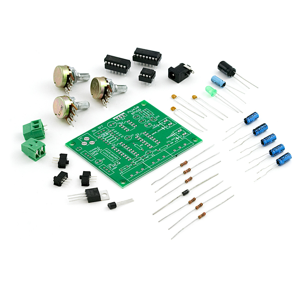
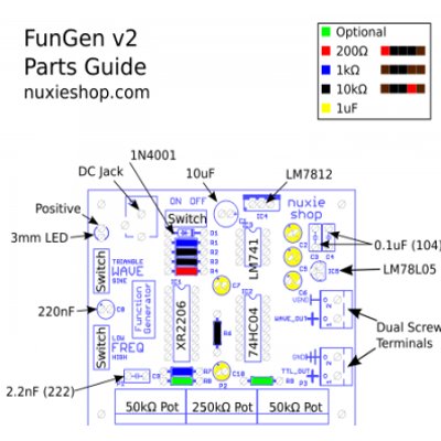
This kit from Nuxie includes everything needed to build a function generator capable of producing sine, triangle and square waves from 25Hz to over 250kHz. An XR2206 IC is used to generate the various waveforms.
Note: This kit requires a ~14V or higher AC or DC 2.1mm center positive wall wart to fully drive the 12V regulator. Any AC or DC wall-wart that outputs 13V or above should work.
Output Waveforms: 5V TTL Square Wave and selectable Sine or Triangle Wave
Output Amplitude: Square Wave: 5Vp-p, Sine/Triangle: 0Vp-p to approximately 6Vp-p.
Output Frequency: 25Hz to over 250kHz using kit components. Can be modified to 0.01Hz to 1MHz.
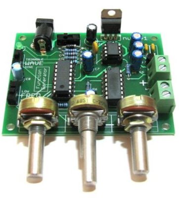
The amplitude and frequency adjustment pots are mounted on the board for easy adjustment. An ON/OFF switch, Waveform selector switch and Frequency range switch are also mounted on the board.
- FunGen PCB
- XR2206 Function Generator IC
- 74HC04 Hex Inverter IC
- LM741 Op Amp IC
- 2.1mm Centre Positive DC Jack
- 100uF or 10uF Cap
- 5 - 1uF Cap
- 2 - 0.1uF Cap
- 0.22uF Cap
- 2.2nF Cap
- 200Ohm Resistor
- 2 - 1kOhm Resistor
- 3 - 10kIhm Resistor
- 1N4001 Diode
- 3 - Slide Switches
- 2 - 50kOhm Potentiometer
- 1 - 250kOhm Potentiometer
- 7812 Voltage Regulator
- 78L05 Voltage Regulator
- 2x Dual Screw Terminal Connectors
Comments
Looking for answers to technical questions?
We welcome your comments and suggestions below. However, if you are looking for solutions to technical questions please see our Technical Assistance page.
Customer Reviews
No reviews yet.
This is a cool little kit. I changed a couple of parts and used the acrylic case the Ipod Shuffles come in as an enclosure.
http://tinyurl.com/ygtqnzk
Just built this kit. Been using Radioshack 273-0332 15V 1000mA adapter as a power supply. Make sure you get the "L" plug to use with the power jack if you do the same.
As built per kit: low freq range was measured at 15Hz to 4.793kHz. high freq range was 996.8Hz to 240.8kHz. Upper end of upper frequency range was very difficult to control with precision. I suspect supplied potentiometers used audio taper instead of linear taper based on in-circuit measurements. Nevertheless, the generator appears to function well.
Might be better to use linear pots or place an additional 1K pot in series with P2 & P3 to provide extra-fine frequency adjustment on high-freq end though that would necessesitate some off-board components. I plan to re-mount this board inside an enclosure and move some of the components off-board anyway.
Optional resistors appear to be parallel with P2 and P3, thus would raise lower frequency limit but not raise upper frequency limit. Better to adjust C8 bigger and C9 smaller if trying to extend frequency range I'd think.
Is there any replacement i can get for this product? D:
Try this guy
thanks man, that really helps alot. come to a point, what do you think about this one? https://www.sparkfun.com/products/11420 it should work well too right? Thanks, Eugene
I should... Honestly I haven't played with it so I can't say for sure, but it looks like it would work great (once you added the Pro Mini)
Just built the kit. My version came with a jack for a 5.5mm x 2.5mm plug (not 2.1mm i.d. as in the description). Also, I used the 12v regulated power supply that sparkfun sells (very cheaply) and put a jumper between the input and output of the 7812 (the two outer pins); use an insulated jumper so that you don't cause a short to ground. Depending on what size jack comes with your kit, you might need to change the plug on the transformer.
Measured 158 Hz to 289 Khz on my ancient nixie-tube era HP frequency counter.
My only complaint is that the frequency is difficult to adjust precisely because of the two single-turn pots. Maybe a high-quality ten-turn pot would be better. But as a cheap and dirty signal source for testing amplifier circuits and things like that, for $30 you can't complain.
Meant to say 15.8 Hz on the low end. Should have previewed, etc.
Assembled quick, like the dual frequency control pots for coarse/fine frequency control. Be aware: output has no DC blocking capacitor, so sine/triangle output has a 6 volt DC offset to ground. The ability to include one on the board (even if not supplied) would have been nice. Also, no series resistor in sine/triangle output so potential for chip damage if output shorted.
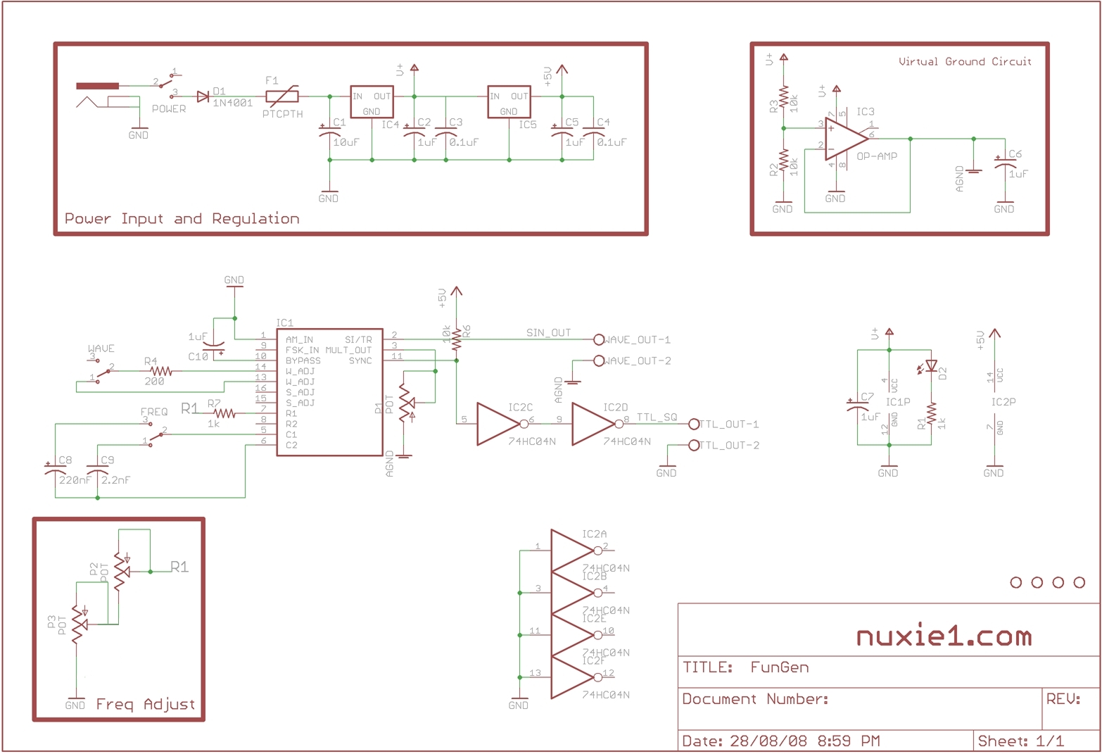
The VGND should be used with the Sin/Tri wave output, this removes the offset. A virtual ground is created with an LM741 opamp chip. A more simple DC blocking capacitor would filter the output (especially the Tri output) depending on load and frequency.
Also, the XR2206 chip has short circuit protection inbuilt, so shorting the output will cause no damage.
Regards,
Nuxie1
How could I modify this to get an output voltage of +-80V?
The question I need to ask is: how much current do you need? Knowing your current requirements is crucial. I had done a shaker table amp years ago using a BGW (750) commercial sound amp panel, though that was rated 250W into 8 ohms, so "only" would have had 65 volt rails. A +-80 volt rail (audio power) amp would be 450W / 8 ohms: there are a few in this category. Or consider building your own high voltage amp around the LM4702, which is rated to +-100 volts with the right version. Be sure your heatsinking is adequate, and observe typical audio power amp grouding/feedback rules so you don't end up with a high power RF oscillator -- until it overheats and shorts out.
I'm working on a portable function generator. Would two 9-volt batteries in series be adequate for power?
As long as you have an 2.1mm adapter and more than 14v, yes
How can this be modified for the .01 Hz?
How can this be modified for the .01 Hz? Did you get an answer to this question ? I would like to know too.
the answer to this depends, in part, on whether or not you want to keep the original range still available. Replacing C8 (220nF) with a larger cap would help achieve the lower frequency but you might have a gap between the lower and upper frequency range if you make C8 too big. You could make C9 (2.2nF) larger as well but would be sacrificing the upper range.
An alternative would be to replace the freq switch with an off board rotary one that allows 3 or more selections instead of the two currently shown. Personally, I'd go with 5 positions (2 low, 2 existing, and 1 high) using caps such as 2200uF, 22uF, 220nF, 2.2nF, and 220pF. Note, the caps are multiples of 100 in values except for the upper one (since the existing board goes to about 240kHz and 1MHz is the stated limit). The high end might be a bit touchy with a smaller cap.
You can also use larger potentiometers to lower the frequency but this will make the frequency more difficult to adjust with precision. To get 0.01Hz, I doubt you could pick a potentiometer with a practical resistance value (would be several Meg I think) so best to stick with modifying the caps.
An unregulated adaptor is fine, as it has onboard +12v and +5v regulators.
Will an unregulated wall unit like this one (GS76H on http://www.maplin.co.uk/Module.aspx?ModuleNo=13453) be suitable, or must it be regulated?