- Home
- Product Categories
- Monochrome
- SparkFun Serial Enabled 16x2 LCD - White on Black 3.3V

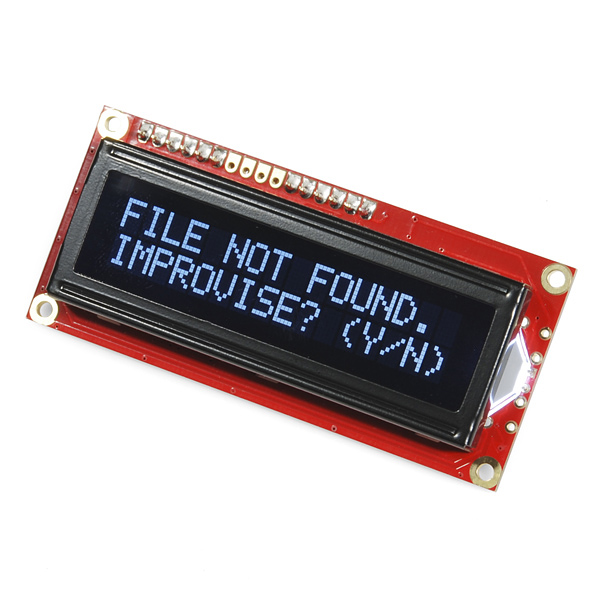
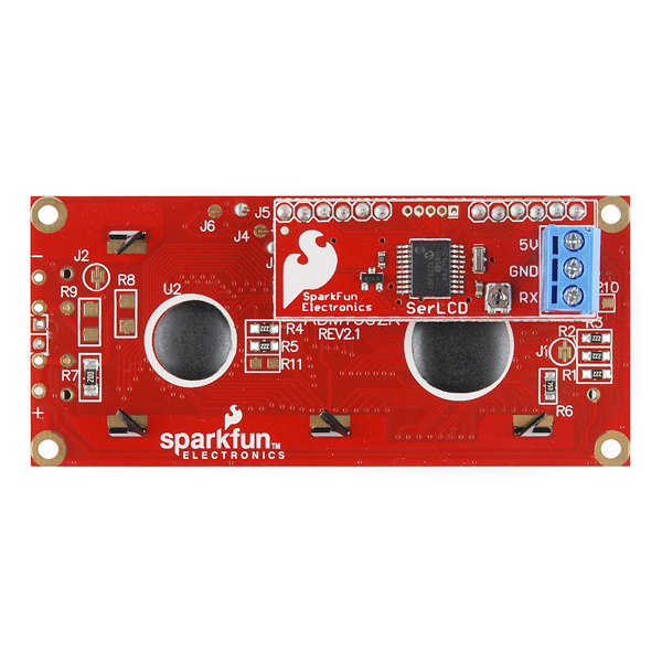
SparkFun Serial Enabled 16x2 LCD - White on Black 3.3V
The serial enabled LCD allows you to control a parallel based LCD over a single-wire serial interface. Included in this product is a white on black 16x2 LCD connected to our serial backpack. The backpack, based around a PIC16LF88, takes a TTL serial input and prints the characters it receives onto the LCD. The installed firmware allows for a number of special commands so you can clear the screen, adjust the backlight brightness, turn the display on/off, and more.
Communication with SerLCD requires 3.3V TTL serial at a default baud rate of 9600bps (8-N-1). You can adjust the baud to any standard rate between 2400 and 38400bps. The power, ground and RX pins are all broken out to a 3.5mm pitch screw terminal.
SerLCD has the ability to dim the backlight to conserve power if needed. There is also a potentiometer on the backpack to adjust the contrast.
Note: Though the silkscreen may say '5V', this is a 3.3v Serial LCD. Connect to a 3.3v power source.
- PIC 16LF88 utilizes onboard UART for greater communication accuracy
- Greater processing speed at 10MHz
- Incoming buffer stores up to 80 characters
- Backlight transistor can handle up to 1A
- Pulse width modulation of backlight allows direct control of backlight brightness and current consumption
- All surface mount design allows a backpack that is half the size of the original
- Faster boot-up time
- Boot-up display can be turned on/off via firmware
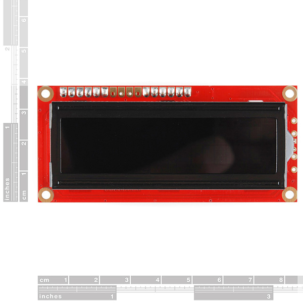
- 1.425x3.15" - 1" Thick
SparkFun Serial Enabled 16x2 LCD - White on Black 3.3V Product Help and Resources
PIC-Based Serial Enabled Character LCD Hookup Guide
May 29, 2018
The PIC-based serial enabled character LCD backpack is a simple and cost effective solution for interfacing to character Liquid Crystal Displays (LCDs) based on the HD44780 controller. The backpack simplifies the number of wires needed and allows your project to display all kinds of text and numbers.
Core Skill: DIY
Whether it's for assembling a kit, hacking an enclosure, or creating your own parts; the DIY skill is all about knowing how to use tools and the techniques associated with them.
Skill Level: Noob - Basic assembly is required. You may need to provide your own basic tools like a screwdriver, hammer or scissors. Power tools or custom parts are not required. Instructions will be included and easy to follow. Sewing may be required, but only with included patterns.
See all skill levels
Core Skill: Programming
If a board needs code or communicates somehow, you're going to need to know how to program or interface with it. The programming skill is all about communication and code.
Skill Level: Rookie - You will need a better fundamental understand of what code is, and how it works. You will be using beginner-level software and development tools like Arduino. You will be dealing directly with code, but numerous examples and libraries are available. Sensors or shields will communicate with serial or TTL.
See all skill levels
Core Skill: Electrical Prototyping
If it requires power, you need to know how much, what all the pins do, and how to hook it up. You may need to reference datasheets, schematics, and know the ins and outs of electronics.
Skill Level: Competent - You will be required to reference a datasheet or schematic to know how to use a component. Your knowledge of a datasheet will only require basic features like power requirements, pinouts, or communications type. Also, you may need a power supply that?s greater than 12V or more than 1A worth of current.
See all skill levels
Comments
Looking for answers to technical questions?
We welcome your comments and suggestions below. However, if you are looking for solutions to technical questions please see our Technical Assistance page.
Customer Reviews
4 out of 5
Based on 8 ratings:
6 of 6 found this helpful:
Decent Little Board
When I purchased this, I read all of the comments both good and bad, and I noticed a lot of really negative shots at this, but even so it's still up and being sold... so why not? I had the money available and I needed it in my latest project, so there wouldn't be a lot of issue with it.
The silk screen incorrectly says 5V, which is prominent at the bottom of the description... I would move that note to the top, guys! This is something I'd request to be changed, at least a sticker or some note in the box, so that confusion doesn't abound. That is the main reason for the loss of a half a star.
Aside from that, this LCD display performed really well, and more or less as advertised. I had a few minor issues wrapping my head around the code that only uses a single wire (as opposed to the multi-wire code that's far more common out there), and some of my favorite little code tidbits didn't like it at all because of that (and so I will be rewriting that code, but I enjoy that, so no biggie).
Adjusting the potentiometer on the backpack is simple, and as with any electronics you'll want to unplug the unit while you make these adjustments. It can seem a little tedious, but I appreciated the "set and forget" logic of it, with the remainder controlled in the software. It actually does make things a lot simpler, firmware-wise.
In playing with the baud rates, there was a slight issue with noise at higher baud rates, but adding capacitors to handle the noise on your breadboard should fix that without issue (the rating of those capacitors will vary based on your project, so don't ask me unless you're providing a detailed schematic and a full copy of the code).
The screw terminal works extremely well with typical jumper wires, and I even took the risk of dangling the LCD screen by one of the wires screwed down. I'm probably going to just leave those in there more or less permanently.
After running the terminal for 8 hours, there was no heat issue at all. The LED on the backlight barely gets warm, which signals a great circuit design and a correct application for the LED. I've owned another LCD where the backlight actually got a bit warm, which isn't overly concerning, but if it's added with heat from other components, it might cause a heat issue with other boards. Not so with this board!
The character output was thoroughly tested, and while I'd prefer a 10-dot height per character, this functions at least as well as anything else I've tried. I loaded up a custom character and there was no issue with display. I even made it move around the display a little, and it worked flawlessly.
Long story short: this is a great product and I'm glad to have it. Now if only we could figure out how to drop the price (the other half-star it lost).
And now for the wish list:
First and foremost: I'd like to be able to query the board, one row at a time, as a serial stream (thus adding a Tx to the board that connects to an Arduino's Rx, making it 4 wires). This simple option would add a level of complexity to the design, but it would be an extremely useful feature.
Second: I'd like to be able to adjust the pot without a screwdriver. I grit my teeth every time metal goes near a live circuit, and it would make setting the pot a lot easier for prototyping purposes (though as a part of a finished product, you certainly would want the pot to stay put). Perhaps including a plastic tool for that wouldn't be hard, but that would certainly up the price, too.
Third: Full libraries for Arduino and Raspian's gcc would be highly desirable, especially those which can easily be added to simplify the unit's operation (e.g., LCD.print() would be awesome, as would a few other common commands). Combined with the existing datasheet, it would make this whole thing much, much simpler and more desirable. And as I don't know enough about what I'm doing yet, it's a vague suggestion at best, and best left to those more skilled than I am. Anything to lower the complexity in the software side would help, honestly, but I think a library would go a long way toward that. The serLCD library on Arduino Playground at the very LEAST needs something linked to the main page, and more comprehensible documentation would help greatly... the bare notes there are hard for a newb like me to follow.
And finally: A lower price. Though this isn't horrible as price goes, I'm a cheapskate, and always looking for the better trade-off between price and performance. And while this is really very decent as it stands, a lower price would be on my wish list, even knowing that it would mean I'd never get one because they'd sell out so fast.
To close, I want to thank SparkFun for such a good little product. There were very few actual issues, but a lot of complaining over a few little caveats that would be resolved if people would just RTFM.
It works.
Easy to use, the backpack takes all the challenge out of actually drawing text to the screen.
However, based on comments and other reviews, I need to knock off 1 star because: The backpack accepts 5V, the LCD accepts 3.3V. After looking all over the device, the voltage listed is 5V on the backpack, which I assume, would fry the device.
3.3V needs to be put on this module, somewhere.
Great product does exactly what I need.
I have never built a project with arduino or using any kind of LCD screens. This was my first and I must say it was a lot easier to do than I expected. The LCD screen is great and does exactly what I needed it to do and was a piece of cake to setup.
Super LCD
I am using this LCD with the Intel Galileo Gen2 and it works great. Even with the TTL being 5V instead of 3.3v it works perfectly.
Great product.
OK display, but one major issue
This display is easy to install and very easy to use, but it has one massive problem: There's a pretty large gap between the backlight and the LCD panel. The problem with that is that the polarization doesn't work as well as it would if the gap wasn't there. I have similar displays where that gap is a lot smaller, and the contrast is much better at higher viewing angles. But with this one, you have to be pretty much straight above the display, otherwise it immediately starts to fade very quickly. The solution would be to either make the acrylics for the backlight much thicker, or to raise the backlight up closer to the panel - none of which can really be done by the user without damaging the display. Otherwise, the display is very well made, although maybe a bit thick if available space is a concern. The logic runs perfectly under 3.3V, as stated in the description, so I don't really understand the other comments that state it would require 5V. That said, the best display is useless if readability, its main purpose, is impacted like that. In its current configuration, this product is therefore absolutely not worth its steep price.
Nice
Works as support files specify. Easy to follow documentation. I used with a PIC24-based system running on 3.3V, no problems. I wish there was a standard mounting bezel available - I had to 3D print my own.
easy to use
This unit is easy to use, and the lib and documents available on the web site is sufficient. The only minor think you need to adjust is the contrast. If not, you may not be able to see the text you send to it.
Works great
Used it for a solder reflow oven I've made. Works good, no issues.
The SerLCD firmware doesn't appear to permit creating custom characters, does it? Unless I've missed something?
I had no problem with custom characters using this LCD purchased a month ago from Sparkfun.
Further to my previous comment, I've discovered that I had not read the item description properly and therefore tried to run the device off a 5V line instead of 3.3V. Obviously with 3.3V the potentiometer is in fact appropriate. Perhaps then, Sparkfun should consider applying a label over the 5V silk-screen just to make it abundantly clear it is a 3.3V device!
This comment is 5 years old, and the "5V" silkscreen marking still hasn't been fixed!? Oh dear, SparkFun...
I've discovered, to my annoyance, that the potentiometer on the serial backpack is too sensitive (too large a resistance range). The LCD arrived in a 'negative' state (wrong contrast) and adjusting it is like brain surgery with the finest movement required to it set it correctly! Not to mention competing with mechanical hysteresis means this pot needs swapping out for a more appropriate-valued one.
Just an FYI for anyone that may have missed this. I did. The 'datasheet' is not very clear and a bit premature in sending you off to the HD77480 datasheet for additional command information. In order to use the 'Clear Display' or 'Move cursor' commands, for instance, you must send the 'special character' 254d first, followed by the corresponding LCD command. These 'special' commands are shown in Section 2, but an example with 254d isn't mentioned until the bottom of section 3 well after a list of extended commands at the start of section 3.3 followed by a non-functioning link off-datasheet to other extended commands. Strongly recommend you browse the firmware source code to really figure out how to send commands/data to the PIC running the display.
I don't understand how you can light a white LED from a 3.3V supply, especially when there's also a transistor in the path. A white LED may require 3.5V up to even 4V. Even at a LED voltage of 3V there's usually too little headroom to control brightness effectively.
I prefer 0.1" headers for low-voltage over screw terminal (whatever the pitch) . So, Sparkfun, be nice guyz and please fix this. :-)
As there was no "delete" for the comment I posted, I am editing this instead. My comment was echoed in my review and so I didn't want to seem superfluous.
You guys should mention that the way to power the back light is through the two "holes" on the side of the lcd labeled on the silk screen with "+" and "-".
That's A way, not necessarily THE way to power the back light. The back light will illuminate when the screw terminal is correctly connected, which also allows for control of the brightness serially.
Anyone know if it is possible to put in Sleep mode the SerLCD? If yess, how?
Maybe attach it to a pin and turn it high to supply 5 volts when a certain thing in the program is true. Then after that print something as well.
I have a serial enabled LCD that I connected to an arduino in the past but now want to get more back to basics using just the AVR chip. I wanted to use it with an AT tiny85 but I think that's not possible. Am I right? I need a chip with USART capabilities? Or is there a way to connect it to a tiny85? Thanks Steve
Sorry if this is a n00b question, but I want to hook this up to my Arduino Duemilanove. I want a connector that will fit in the input of this screen without soldering. Also, what code can I use to print, i.e. Hello World?
Since it is a screw terminal on the screen, you can use jumper wires to connect to the screen without soldering. In regards to printing "Hello World", check out the example code at http://www.arduino.cc/playground/Learning/SparkFunSerLCD
The hex file is not the same as the one burnt in the unit. Please disclose the same working c source for this unit, which is exactly used for the hex burnt inside.
Please, please.
Otherwise, don't buy it. You can not make your changes unless you find what they did distill or hide.
I have ported LiquidCrystal library for use with the serial LCD you can look at my code here. Still working on finishing all the documentation. But putting up for now hopefully someone will find it usefull.
http://arduino.cc/playground/Code/SerLCD
-Thanks
using MPLAB with PICKit 3, I could load the modified version which was from serLCD-v2.7, however, it did not work for some reasons. After that, I reloaded the orginal firmware from SerLCD-v2.zip. Neither did it work. I doubt the firmware and source code are not the working version. Any ideas.
what is the compiler or tool chain for serLCD-v2? I'm new to this pic development environment. Please give me the list of steps for setup since I want to modify this firmware for my application.
thanks.
We used CC5X to write the code for this device. If you're new to PIC programming, you might want to start with something easier than this board; you'd have to get the LCD and serial port working in the blind, which may not be easy.
I made some changes to show my particular message on the screen. How can load .hex (It is intel hex format?) into PIC16F88 thru PICKit 3. I do have PICkit 3. Thanks for your information.
Mike, Thanks for your quick response. I got one serial LCD
LCD-09067 yesterday. Does CC5X support 32bit variables? Can I use MPLAB to compile your source code?
Aslo, I want to use very small LCD just like SCD55104A from OSRAMP Opto? Do you carry such small LCD or LED (at least 8 chars)?
Thanks.
main points for a Netduino+ user:
1. call port.Flush() following every call. closing the port doesnt guarantee it will happen. go figure. YMMV.
2. COM1 consists of digital pins 0&1 with 1 being the only one to hook up with this board. (com2 == pins 2&3)
those small pieces of info would have gone a long way to making it easier for this newb.
other points:
notice there are two command bytes for different commands...0xFE and Ox7C
the potentiometer on the back is not overly sensitive as someone pointed out. when i finally figured out what it was.
make sure you drive it with 3.3V even though it says 5V on the back. mine didnt burn out or anything when i did it, but it was obvious.
Is it just me or does this thing not save baud rate changes? The datasheet claims that changes to the baud rate and splash screen are saved in the EEPROM, but when I change the baud (I know it changed because I can communicate at the new baud) and then restart the LCD it reverts to 9600 baud.
Ensure that you're not sending it characters when it starts up. It has a built-in recovery mode where if it receives characters during startup, it will revert to 9600 baud.
This screen is a true pain in my ass. I've spent hours debugging it, only to realize that when using arduino hardware Serial, the screen gets sent random characters when programming the arduino. This causes the screen to get into a wacky state, requiring not only a full power reset of the device (unplugging usb), but also requires shorting power and ground to the screen so that any caps get discharged.
Sparkfun needs to update the firmware for the serial driver they have built, because this is really absurd.
Yea yea, i know what the response will be, SW serial. lame.
other than that, a $30 Serial LCD? oh that's cool!
If you disconnect the RX line on the LCD while programming the Arduino, this should fix the problem you are having with the screen. Keeping the RX line connected can lead to garbling the firmware on the LCD, because of exactly what you mentioned.
I ordered this for an aerodesign project at Boise State. We have a competition in < 3 weeks.
I have this interfaced to an ATxmega128A1. I can write to it fine, but what I am finding is that it is a bit sensitive. Also, when the PIC gets confused, there is no recovery. Since this is a one way communication, there is no way to tell if the display is messed up or not. I'm finding this to be a pretty severe issue.
When I power up my system, sometimes i get glitches on the LCD screen. Often when I write things to the screen, I get odd results. This is at 9600Baud.. seriously??? I communicate over serial lines at > 400Kbps, this should be a piece of cake.
To be honest, the glitches don't happen that often, but I am concerned that they happen at all, and that I cannot recover the LCD. I have a command to try and send all of the reset codes to it, but nothing works. Once the PIC goes off into the weeds, I cannot recover it. Is there some sort of reset sequence I can try?
At this point, the LCD is probably "good enough", but I really dislike a state machine that locks up hard and won't recover.
FWIW - I am using 3.3V, verified and tested. I do have a wire harness, which is about 2 feet long. I added a cap between ground and the RX line because without that, I was getting terrible noise and lots of errors on the LCD. More garbage than clean characters.
I am sure that there is some coupling of noise from the RX line to the power, but, are there no caps on the board?? Okay, a quick check of the board shows that.. there is a single 0.1uf cap. Wow.. hardly adequate. Maybe I'll put something heftier on the board for power..
Never mind.. I put some crazy big caps on the power and it does not help. I need a cap between RX and Ground to get the thing to work at all..
Hopefully I'm making some simple mistake, so if anyone can point out what I'm doing wrong - I'll be grateful.. it's always possible I got a bad unit.. stuff does happen.
i bought this yesterday and made my own clock with it. I wonder how could i change the contrast of screen? (not backlight)
oh and i forgot; what is the max current draw of this one? ive used it with fdti chips 3v3 out pin and its looks fine with fully backlight on, but still im curious about it
*** distilled datasheet ***
Position Indexes:
Line 1: 128 to 143 (16 chars)
Line 2: 192 to 207 (16 chars)
here is the fastest way to get up and running:
include
define txPin 2
SoftwareSerial LCD = SoftwareSerial(0, txPin);
// don't need rxPin for an LCD (0)
void setup()
{
pinMode(txPin, OUTPUT);
LCD.begin(9600);
}
void loop()
{
//To clear the Screen
LCD.print(0xFE, BYTE);
LCD.print(0x01, BYTE);
//Move to beginning of second line (192)
LCD.print(0xFE, BYTE);
LCD.print(192, BYTE);
LCD.print("Hello world!");
//Set the light level (range is 128-157)
LCD.print(0x7C, BYTE); //backlight command flag
LCD.print(157, BYTE); //light level max
}
Slick looking display, and it's easy to use. This white/black version is also more readable outdoors and in vehicles than the black/green version I had previously used. They both seem to have some issue with polarized sunglasses at certain angles, but this white/black one seems much better during my initial tests.
While I really like this LCD, I've discovered that it has a nasty habit of trying to power itself off the serial data line when the power (5V line) is disconnected. This overloads the output pin on my controller, usually rendering an $8 chip inert.
I checked my circuit for any obvious problems, but it's pretty hard to get confused when you're only dealing with three wires and one of them's unplugged.
Are you using this exact display? Because it clearly states that it requires 3.3v not the 5v the silkscreen claims.
Regarding sucking power from the serial port, I've discovered the same thing. It hasn't damaged my micro yet, but I suppose it could (an ADuC).
I would like to connect the Arduino Pro 328 a Serial Enabled 16x2 LCD.
This gives no problems with the debugging because the TXD also used?
I'm new to this and found the datasheet unclear and inconsistent about how to clear screen etc.
Serial.print(0x7C, BYTE);
Serial.print(0x01, BYTE);
Just wasn't doing it!
Several hours of searching finally answered the question! to clear the screen you use this;
Serial.print(0xFE, BYTE);
Serial.print(0x01, BYTE);
A really useful explanation and more info is to be found here;
http://www.arduino.cc/playground/Learning/SparkFunSerLCD
No author mentioned, but thanks whoever you are! :-)
in BASH on a beaglebone if I echo -e "\xFE\X01" > /dev/ttyO1 it clears the screen but I have 5 vertical lines (in character 1 off on off on off, and in character 2 on off on off on) instead of a clear screen