- Home
- Product Categories
- DC/Gearmotor Driver
- Motor Driver 15A IRF7862PBF

Motor Driver 15A IRF7862PBF
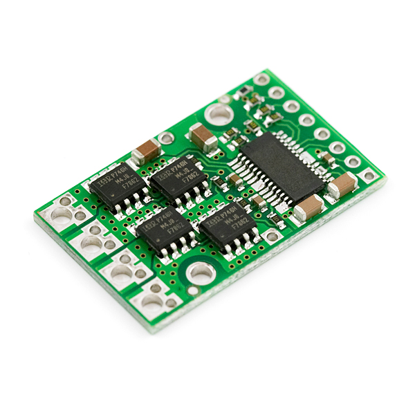
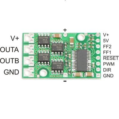
The Pololu 15 Amp high-power motor driver is a discrete MOSFET H-bridge designed to drive one DC brushed motor. The H-bridge is made up of one N-channel MOSFET per leg, and most of the board’s performance is determined by these MOSFETs (the rest of the board contains the circuitry to take user inputs and control the MOSFETs). The board supports a wide 5.5 to 24 V voltage range and is efficient enough to deliver a continuous 15 A without a heat sink, or 21 A with a heat sink.
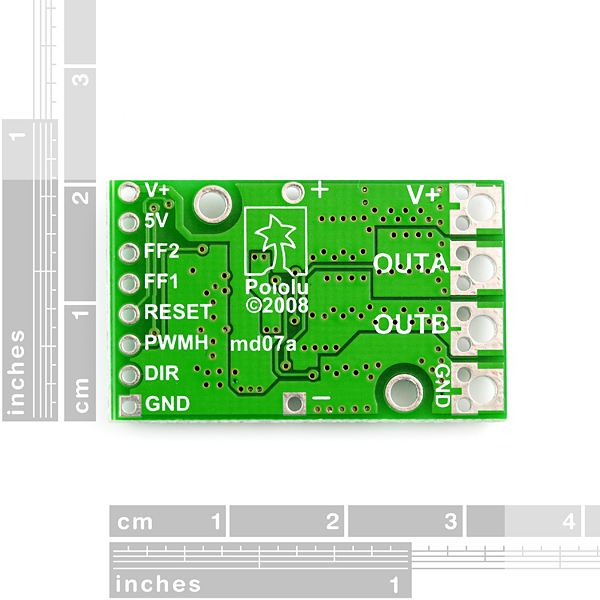
With the PWM pin held low, both motor outputs will be held low (a brake operation). With PWM high, the motor outputs will be driven according to the DIR input. This allows two modes of operation: sign-magnitude, in which the PWM duty cycle controls the speed of the motor and DIR controls the direction, and locked-antiphase, in which a pulse-width-modulated signal is applied to the DIR pin with PWM held high.
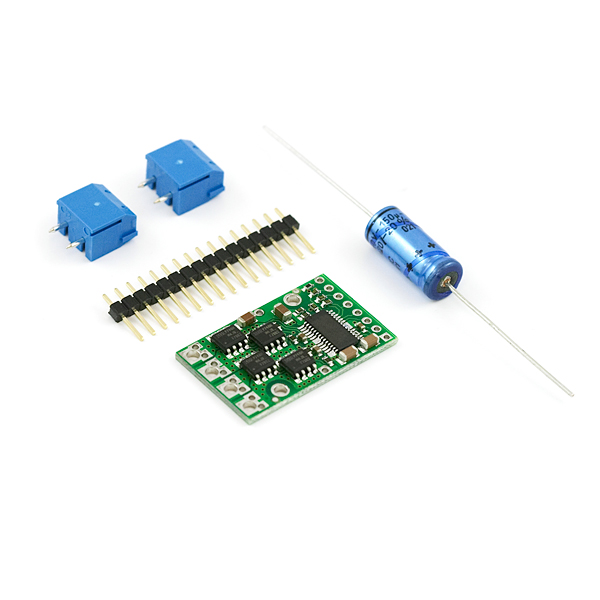
The included axial capacitor should be mounted to the + and - holes in the middle of the PCB. Make sure the cap is connected with the correct orientation.
Note: Batteries that are nominally 24 V can be much higher than that when fully charged; this product is therefore not recommended for use with 24 V batteries unless appropriate measures are taken to limit the peak voltage.
- IRF7862PBF MOSFETs Motor Driver
- 1 Motor Channel
- Operating Voltage: 5.5 - 24V
- Continuous output current: 15 Amps
- Peak output current: 170 Amps
- Max PWM frequency: 40kHz
- MOSFET on-resistance: 3.7mOhm
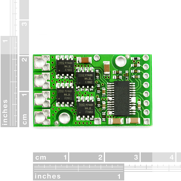
- 1.3" x 0.8"
- Datasheet (IRF7862PBF)
- Pololu Page
Motor Driver 15A IRF7862PBF Product Help and Resources
Core Skill: Soldering
This skill defines how difficult the soldering is on a particular product. It might be a couple simple solder joints, or require special reflow tools.
Skill Level: Noob - Some basic soldering is required, but it is limited to a just a few pins, basic through-hole soldering, and couple (if any) polarized components. A basic soldering iron is all you should need.
See all skill levels
Core Skill: Robotics
This skill concerns mechanical and robotics knowledge. You may need to know how mechanical parts interact, how motors work, or how to use motor drivers and controllers.
Skill Level: Rookie - You will be required to know some basics about motors, basic motor drivers and how simple robotic motion can be accomplished.
See all skill levels
Core Skill: DIY
Whether it's for assembling a kit, hacking an enclosure, or creating your own parts; the DIY skill is all about knowing how to use tools and the techniques associated with them.
Skill Level: Noob - Basic assembly is required. You may need to provide your own basic tools like a screwdriver, hammer or scissors. Power tools or custom parts are not required. Instructions will be included and easy to follow. Sewing may be required, but only with included patterns.
See all skill levels
Core Skill: Programming
If a board needs code or communicates somehow, you're going to need to know how to program or interface with it. The programming skill is all about communication and code.
Skill Level: Rookie - You will need a better fundamental understand of what code is, and how it works. You will be using beginner-level software and development tools like Arduino. You will be dealing directly with code, but numerous examples and libraries are available. Sensors or shields will communicate with serial or TTL.
See all skill levels
Core Skill: Electrical Prototyping
If it requires power, you need to know how much, what all the pins do, and how to hook it up. You may need to reference datasheets, schematics, and know the ins and outs of electronics.
Skill Level: Competent - You will be required to reference a datasheet or schematic to know how to use a component. Your knowledge of a datasheet will only require basic features like power requirements, pinouts, or communications type. Also, you may need a power supply that?s greater than 12V or more than 1A worth of current.
See all skill levels
Comments
Looking for answers to technical questions?
We welcome your comments and suggestions below. However, if you are looking for solutions to technical questions please see our Technical Assistance page.
Customer Reviews
4.7 out of 5
Based on 3 ratings:
Overkill brings peace of mind
I'm using this controller to drive a thermoelectric cooler module rated at 5A at 12 V. I'm cooling or heating a small laser diode module from 0 to 50C. Since the thermal mass is low, I usually only use 6V for the supply. As a result, module that can handle 15A air 24V is quite a bit of overkill. On the other hand, I don't have to worry about overheating the driver module---as I have done with some robotics projects in the past.
One small annoyance has shown up--I have to be careful about power sequencing at startup. I think the module wants stable low PWM and direction inputs at startup, so i have to make sure to turn on its power supply before I start the micro controller providing the PWM and DIR inputs.
I did find out that thermoelectric modules don't like pure PWM inputs---they lose a LOT of efficiency. Because of this, I had to add a filter section with 47uH inductors and 100uF capacitors between the motor driver and the thermoelectric cooler module.
Great Driver
Works as advertised even pushing past 15A does not get hot.
best motor driver
Easy to use, and very small. and the quality is very good.
Has anyone used this with a Raspberry PI? If so do you have any insights on the correct wiring scheme, and the software package you used for PWM control. I think I have it wired up correctly, but am getting no response.
Try the following link for board description and operation:
http://www.pololu.com/catalog/product/755
I agree with jepler. I would have been nice to know what the 28-pin IC is. If it is the Allegro A3941 then it will have up to 14 mA quiesent current draw.
Yep, the chip label is actually scratched out, the pictures are not edited. So your guess is as good as ours at to what the chip actually is.
While I can't rule out that it's another similar chip, the location of the charge pump caps and the FF1/FF2/Reset lines make it seem a likely candidate to me.
I was interested in this question not because of the quiescent current, but because I wondered what part is the reason for the voltage limit. The IRF power MOSFETs are good to 30Vds. So did they skimp on the caps (25V parts)? or conservatively derate the MOSFETs? Inquiring minds want to know!
The MOSFETs have an absolute maximum voltage rating of 30 V, and higher voltages can permanently destroy the motor driver. Under normal operating conditions, ripple voltage on the supply line can raise the maximum voltage to more than the average or intended voltage, so a safe maximum voltage is approximately 24 V. The absolute maximum operating voltage for the board is 30 V.
Too bad the 28-pin IC's part number is blocked out. Based on function and layout, it must be something like Allegro A3941 (a 50V-capable part).
This motor driver is awesome. I'm using it to feed 3.3 Amps to a 12V motor and it doesn't heat up at all! They are a little bit pricey though, ever consider stocking these:
http://www.pololu.com/product/1451/specs
Hello All, where can i find schema and eagle files for this product ?
I'm also looking the schematic of this so I can fix a board I have. Can't find it at Pololu. :(
Yes, I, too, would like to see the schematic of this. Pololu doesn't make their schematics very public. Anyone find one on this?
Check the Pololu link above. They manufacture this board so the files should be there.
Question!
I want to control 4 DC brush motors, I don't need them to run at the same time... Ever, but I do need to be able to control the speed of each one, when one is on. SO...
To save money, can I just run the output of this controller and split to 4 individual N channel mosfets, each mosfet will control one of the dc brush motors, then use 4 arduino pins to turn each individual motor on and off?
Is there a way to smooth the pwm on the output going to the motor? I'm using the pwm to slow my motor, and would like to cut down the motor noise. I tried putting a capacitor on the pwm that controls the MOSFETS, but that made it difficult to control the speed.
Either put a cap on the output of the controller (between the motor leads) or increase your PWM frequency.
The description states that this is "designed to drive one DC brushed motor." Will it work on brushless?
I know that is a newbie question, but I am what I am... and what I am is trying to find something to drive a 12V 7.5A diaphragm pump which, according to the spec sheet, is using a brushless motor and I am wondering if this will work.
Brushless motors have three phases that need to be controlled properly in order to get them to spin, and each of those three phases needs half of an H-bridge to drive it. This board has two half-bridges, so you're short one. You may be able to make it work with two of these boards, however, you'd still be left with a lot of work to actually drive the boards in the proper sequence from an external microcontroller, and for a newbie that might be more than you want to bite off (or it might not, if you're ambitious, by all means go for it!)
SFE doesn't currently carry anything that makes this particularly easy, but depending on your budget you might look at purpose-built brushless-motor driver boards from others. There are a number of these available for the radio control market (typically called ESC for Electronic Speed Controller), as well as brushless-motor driver boards of all sizes for the robotics market. Good luck!
It seems that this driver can be used to control a TEC, specifically the 15V 7A sold by sparkfun. Other controllers seem to be underpowered. Am I right about that?
Hi... i bought two of Motor Driver 15A IRF7862PBF from india.one is working fine but the other motor driver is not working properly even the connections and data are given correctly.But my observation with not working Motor driver is even when the V+ and Gnd of motor power is not connected with the power,the voltage between +V and Gnd is 4.00 V and voltage between Gnd and Motor OUT A is 1.01 V and the same is with Motor OUT B existing.This is not in the case of working one.What can be a problem with my second motor driver?
I can feed this circuit with a battery of 12V/700mA and obtain in the out of driver 15A that says datasheet? the circuit can generate this current output without the power supply gives that current?
Has anyone used this? Does it work fine?
Thank you!
This motor driver was released more than 2.5 years ago, so I think someone has probably used it by now ;) And yes, it does actually function as specified in the product description. A more detailed description and usage instructions are available on Pololu's page for this product.
Thanks Ben. Well I am making a DC servo motor controller circuit. The encoder signals have been taken care of but driving the motor has become a problem with the ordinary ICs like L293, L298, LMD18200, etc. as the motor ratings are 60W, 24V, 3.7A, 3000 rpm. Is there any better motor driver than this one for the my motor? Help buddy!
I would not recommend powering this motor driver from a 24 V battery. If you want something that will work in a 24 V system, Pololu carries higher-voltage versions of this driver and motor controllers with similar power outputs and higher-level interfaces (see the Simple Motor Controllers).
If your goal is to make a servo, have you considered the jrk 21v3 motor controller with feedback? If your servo uses analog voltage feedback, it sounds like that might be perfect for you.
Thanks Ben for the reply.
Can 4 of this drivers be handled by the IOIO Board over PWM and seperated Power Supply ?
If so, is it enough connecting a PWM OUT from the IOIO to an PWM IN on the Driver Board ?
Thanks in advance!
According to the data sheet, shown by jthendean, the motor driver will push supply 21A continuously if you can affix a heat sink to it. Has anyone had luck with this? I'm designing an enclosure for it and I'd like to heat sink it, but give the assembly as shown I wasn't sure if I should affix the heat sink to the bottom or the top of the board. Thoughts?
Affixing it to the bottom risks shorting together different nodes if you're not very careful. I think you should put the heat sink along the tops of the four MOSFET packages as those are what you are ultimately trying to keep from overheating.
I connected PWM and DIR to Arduino. I connected the two wires from the motor to OUTA and OUTB, 12v. to V+ on the motor power side and I grounded it. I also supplied 5V to the V+ on the logic pin side and grounded it as well. I connected PWM pin from the motor driver to the PWM pin on Arduino and the DIR pin (motor driver) to a non PWM digital pin. I programed it so that it changes directions every 2 seconds.
When I turn on the 12V power supply, the power for arduino comes on as well. The motor does not turn until I plug in the USB cable for Arduino. It rotates in the speed that I expect for 2 seconds and then it starts to vibrate. The power light is dim with just with the power supply and when I plug the USB cable, it becomes brighter. If the USB is already plugged and if I plug the 12v power supply, the motor turns extremely slowly and it vibrates as well.
What am I doing wrong?
I would really appreciate a response.
Thanks.
This is of course late, but for future reference, I believe that you shouldn't hook up the logic side's V+ to a 5V power. According to pololu 'V+ pad on the logic side of the board gives you access to monitor the motor’s power supply'. Also since they mention the 5V line being able to supply a regulated 5V, my assumption is that the chip has a built in regulator that takes the Vin and supplies 5V to all the logic components. My reference is pololu's website for this product: http://www.pololu.com/catalog/product/755
Looks like the A3941 MOSFET driver. The FF1 and FF2 error outputs are the same as are the DIR and PWM style inputs. Plus pins 7-8, 13-14 and 17-18 are tied on the 3941.
Do you have a link to a datasheet for the board, not just for the FET?
Try the following link for board description and operation:
http://www.pololu.com/catalog/product/755
datasheet link is busted and description reads like it can both control more than one motor, but also specifically says it can control only one motor, which is confusing.
Link is fixed. Thanks for pointing that out!