- Home
- Product Categories
- Development Tools
- Breakout Board for PIC24HJ64 - mini-Bully

Breakout Board for PIC24HJ64 - mini-Bully
Replacement: None. We are no longer carrying the mini-Bully in our catalog. This page is for reference only.
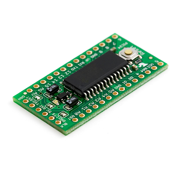
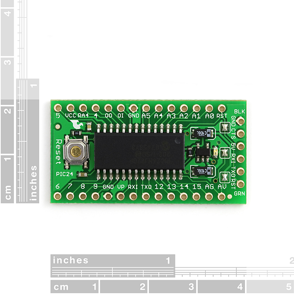
The 'mini-Bully' is a simple breakout for the very powerful 16-bit PIC24HJ64 microcontroller. The board has a 3.3V regulator and runs a serial bootloader developed by Mississippi State (the 'Bull Dogs'). The mini-Bully comes fully assembled as shown without connectors populated so that you can solder in any connector or wire with any orientation you need. No programmer required, only a serial connection provided by the USB-to-Serial (TTL) cable such as the FTDI Basic board listed below.
PIC24 code examples that are compatible with the mini-Bully and source code for the bootloader can be found here.
- PIC24HJ64GP502, 64K flash, 8K RAM, 40MIPs from internal PLL, DMA, 5 timers, 2 UARTS, 2 SPI, ECAN, I2C, RTCC, 10/12 bit ADC, analog comparator
- Low-voltage board needs no interfacing circuitry to popular 3.3V devices and modules (GPS, accelerometers, sensors, etc)
- Program using serial/USB connection off board
- Supports auto-reset
- 3.3V regulator
- Reverse polarity protected
- DC input 3.3V up to 12V
- On board Power/Status LED
- 0.17 x 0.83 x 1.55" (4.2 x 21 x 39.5mm)
- Schematic
- Bootloader
- Firmware
- Datasheet (PIC24HJ64)
- Video Tutorial
- A good tutorial showing Kalman Filter stabilization using mini-Bully and the SparkFun 5DOF
Comments
Looking for answers to technical questions?
We welcome your comments and suggestions below. However, if you are looking for solutions to technical questions please see our Technical Assistance page.
Customer Reviews
No reviews yet.
I can't connect to MPLAB ICD 3. Target Device expected error. I have put the miniBully in a bread board and I tried with ICSP Adapter plus male-male jumpers and then with Sparkfun mini ICSP connector in the back of mini Bully. Always the same error. Did some of you program or debug this board with MPLAB ICD 3?
The same with a 2nd miniBully.
I have no other board with ICD2 connector to try in. I am thinking to buy a simple eval board from Microchip to try again and see what I am doing wrong.
Help me, please!
Thanks
I have not tested it with an ICD3. However, it works fine with a PICKit2 and Sparkfun connector adapter. If it works with one ICSP device, not sure why it would not work with another one. Without a serial cable plugged in, it is just a breakout board, with all of the pins accessible.
Thanks rbreesems,
I have tested with a Microchip "28-pin Starter Development board" and the error persists. Try ICD2 and ICSP connector as well to mini ICSP port in mini-Bully.
I have connected every pin from the breakout of this board to all the pins in the mini-Bully board.
Always the same error: Target Device Mismatch.
PIC24 and dsPIB33 chips plugged in the 28-pin Microchip Board works at first time, Target ID response OK in MPLAB ICD plug in MPLAB Studio 8.4
I really want debug/program mini-Bully with ICD3, but now it's impossible. I don't know what I am doing wrong.
If someone make MPLAB ICD3/mini-Bully works, please tell us!
Thanks
This is late, but I can also confirm that this does not work with ICD3, but works fine with ICD2. I even tried replacing the 1k pullup on MCLR to 4.7k and that did not help.
When you have ICD3 power the device, the LED to go bright for a split second, then go to dim. Checking the supply voltage, it is around 1.7 Volts. Taking the device out of reset does the same: bright LED then dim. So it seems like it initially has the correct voltage then the voltage collapses.
Powering the MiniBully separately does not help either. Still have a connection error even if the PIC now has 3.3V supply.
Hope that helps someone.
-Vince
I was having the same problem with a REAL ICE then replaced the 1k resistor with a 15k resistor and all is well. ICD3 will probably respond similarly. The board is powered separately as REAL ICE will not power the board. Regards
Thanks Mr. Reese and please let us know if Microchip respond to ticket you opened.
Yap, on '64GP502 device all pins have open drain feature.
Errata in datasheets - OK, but these seems to me like a too
big mistake for FRM document.
Finally, if a person is not convinced that RB15 on the PIC24HJ64GP502 supports open drain then the heartbeat LED can be blinked by setting LATB15 = 0, and then toggling the TRISB15 bit (changing the port from input to output). When the port is an input, the pullup resistor will power the LED, when the port is an output, the LED will be turned off. The source code library linked to this part have the heartbeat functions as macros, and these are easily changed by the user.
There is already an inconsistency between the datasheet and what the PIC24 FRM says - pins PORTB RB15-RB11 on the p24HJ32GP202 has analog functionality which the PIC24 FRM says precludes open-drain functionality, and yet the p24HJ32GP202 datasheet shows open drain supported on these pins. So, which do you believe, the FRM or the datasheet or the compiler header files or direct chip experimentation (the last three show that open-drain is supported)? If you accept that the p24HJ32GP202 does support open-drain on all PORTB pins (i.e., believe the datasheet and direct experimentation), then why would the p24HJ64GP502 be purposefully designed to not support open-drain on these same pins? These two devices, the p24HJ64GP502 and the p24HJ32GP202, are supposed to be pin compatible from a parallel port I/O standpoint, regardless of what the p24HJ64GP502 datasheet says. This would be not be the first time that I have encountered datasheet errata. Anyway, a ticket resolution on this will not happen until after the Master's conference, so not until the beginning of August.
Well, according to datasheets, port structure is not the same on these two PICs. 24HJ32GP202 has open drain feature on all PORTA pins (pins 0 to 4) and on all PORTB pins, while 24HJ64GP502 has OD feature only on PORTB pins 5-11 (which are 5V tolerant and not an AD channels) and neither of PORTA pins.
I also looked in errata, but nothing about this...
Installed the newest version of C compiler but .h file is still the same...
Of course, RB15 has OD feature. I'll do experiments with other pins these days...
I also posted a question on microchip forum but still no answer...
http://www.microchip.com/forums/tm.aspx?m=435749
tomcuga: 24h FRM, section 10 I/O ports, page 10-4:
"The open-drain I/O feature is not
supported on pins that have analog functionality multiplexed on the pin"
Pin RB15 is analog channel AN9.
Also in PIC24HJ64GPx02/x04 datasheet (DS70293C)on page 43, table 4-29 only pins 5 to 11 have open drain feature
implemented.
Interesting. The DS70289D datasheet for the PIC24HJ32GP202, pg 36, Table 4-18 shows all of the open-drain bits for PORTB defined. The only difference between the PIC24HJ32GP202 and PIC24HJ64GP502 is the memory size and DMA module support, the port structure is the same. I have a ticket into Microchip to resolve this. I have tested both the PIC24HJ32GP202 and PIC24HJ64GP502 and direct experimentation shows that open drain is supported on RB15.
tomcuga: Open drain feature on pin RB15 is not supported on PIC24HJ64GP502. So this pin is maybe not good choice for power/heartbeat combination LED.
An additional comment - on my breadboard system at home with a PIC24HJ64GP502, I hooked up the power/heartbeat LED in a direct drive configuration (resistor in series with LED). With RB15 configured for open drain, the LED did not blink which is what you would expect since the output floats when driven high in open drain mode (the LED blinked when RB15 was configured as a normal output). So this confirms that RB15 does support open drain mode.
tomcuga: Open drain feature on pin RB15 is not supported on PIC24HJ64GP502. So this pin is maybe not good choice for power/heartbeat combination LED.
Why do you say this? In the p24HJ64GP502.h header file, the open drain configuration bit is included for all bits of PORTB, and for bits 0-4 of PORTA. It is true that RB15 is not 5V tolerant, but it can still be configured as open drain, and the power for the power/heartbeat LED is 3.3V. Also, I can't find anywhere in the datasheet for the PIC24HJGP502 where is says open drain is not supported for RB15.
24h FRM, section 10 I/O ports, page 10-4:
"The open-drain I/O feature is not
supported on pins that have analog functionality multiplexed on the pin"
Pin RB15 is analog channel AN9.
Also in PIC24HJ64GPx02/x04 datasheet (DS70293C)on page 43, table 4-29 only pins 5 to 11 have open drain feature
implemented.
Open drain feature on pin RB15 is not supported on PIC24HJ64GP502. So this pin is maybe not good choice for power/heartbeat combination LED.
The datasheet link looks like it was fixed. Agreed it needs to be 64K flash memory. From the full PDF datasheet, the only members of this particular sub-branch that have 4K RAM are the PIC24HJ32GP304/302. All of the other members including the PIC24HJ64GP502 have 8K RAM, and the memory gauge in MPLAB confirms this.
I've found some problems in the spec: Broken datasheet link; From microchip's site: PIC24HJ64GP502, 64K flash, 4K RAM http://www.microchip.com/wwwproducts/Devices.aspx?dDocName=en534556