- Home
- SparkFun On Screen Display Breakout - MAX7456

SparkFun On Screen Display Breakout - MAX7456
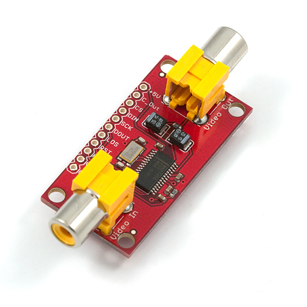
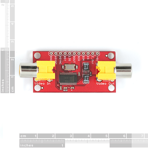
This is a breakout board for the Maxim MAX7456 monochrome on-screen display chip. The board is set up with all supporting circuitry and RCA connectors to allow the user to easily interrupt and overlay text and/or graphics onto a video signal (PAL or NTSC). Just plug in your video signal to "Video In", plug your TV into "Video Out", connect a microcontroller to the SPI interface and supply the board with 5V@100mA (worst case) and you're good to go. Supplied sample code runs on an ATMega168/328 (16MHz) and compiles with WinAVR, so it's just about "plug-and-play" with an Arduino board.
**Weight: **0.30 ounces, 8.6 grams
- Input voltage 5V
- Current consumption 100mA, worst case
- 5V SPI interface
- 1.8x0.9"
- Schematic
- Eagle Files
- Datasheet (MAX7456)
- GitHub (Design Files & Example Code)
SparkFun On Screen Display Breakout - MAX7456 Product Help and Resources
Core Skill: Soldering
This skill defines how difficult the soldering is on a particular product. It might be a couple simple solder joints, or require special reflow tools.
Skill Level: Noob - Some basic soldering is required, but it is limited to a just a few pins, basic through-hole soldering, and couple (if any) polarized components. A basic soldering iron is all you should need.
See all skill levels
Core Skill: Electrical Prototyping
If it requires power, you need to know how much, what all the pins do, and how to hook it up. You may need to reference datasheets, schematics, and know the ins and outs of electronics.
Skill Level: Rookie - You may be required to know a bit more about the component, such as orientation, or how to hook it up, in addition to power requirements. You will need to understand polarized components.
See all skill levels
Comments
Looking for answers to technical questions?
We welcome your comments and suggestions below. However, if you are looking for solutions to technical questions please see our Technical Assistance page.
Customer Reviews
4 out of 5
Based on 1 ratings:
Drop the price $10?
About $10 to much $$.
Any chance we could get the blank PCB only?
If you're thinking of bypassing the RCA jacks by tacking wires onto the pads on the solder side of the board, beware that the RCA jacks are SHORTING JACKS for some reason. Without a plug in the jack, the video is shorted to ground.
This thing is a piece of crap! I have researched everything about this, used several libraries, codes, and still all I get is video, no overlay. either I have a bad unit or,as I suspect from other comments, this chip has BOB as flaws
I was hoping there may be someone that can help me out. I am able to get my video to pass through this, but i am unable to get any text displayed. I appear to have it wired as suggested. Including connecting the RESET to 5v. Anyone else have this issue and find a solution? (I have tried many different libraries and code examples, and none seem to work...)
I had a little trouble getting the sample code to work with Arduino 1.5.4 for some reason. I had to put the .h and .cpp files in the same folder as the sketch to get it to compile. Before that, I would just get MAX7456 does not name a type OSD errors
Anybody gotten this thing to work with PICAXE?
Any help at all would be appreciated
What would be the bare MINIMUM products to order with this item to have this work on a 12v CCDTV system? I would like to build something like a mini DVR but I am not very fluent with code and would not know where to start with ordering what would be needed! :(
Any and all help is greatly appreciated!
P.S. Schematic is not working for me.. Also, is there anyway to get the eagle files for this board??
Any Documentation for the library please.... I want to display a text on any s,y i chose how to do that
The project have been moved to a new thread. Should be plug-n-play with Arduino and this breakout-board. The new thread can be found here: link
Thought I'd share this...here is a cool OSD project that someone is working on with this.
Hi All, Characters always appear at the top right hand corner of my screen.... has anyone else had this issue?
I am trying to integrate with a Netburner 5213 micro. It has a QSPI (Queued SPI) interface that I am using and have written a C++ program modeled after the sample code.
I am able to communicate, i.e. change the character and make it blink, but it seems like in is stuck at position 0. Any ideas?
Thanks for any help!
Has anyone been successful in connecting this up to an arduino who is willing to share their code and schematic?
Any idea on when you'll build and have back in stock???? Thanks
There's 28 in stock at the time of this writing. Are you looking for greater numbers, or did they just happen to restock it after your comment? :)
Of course after the request, and just one. SpkFun Eng's were asleep at the keys, little shake and now 26 left ;)
Is it possible to use the with the Arduino TVout Library? I have a project I am working on at work and was going to use the Nootropic Design Video Experimenter (http://nootropicdesign.com/ve/) but we are having issues getting them listed as a vendor.
I am getting problem in output overlaid video. The whole screen is filled with white dots in grid pattern (i.e. in all display areas) when I power on MAX 7456. Even the dots are present when I display some character on the screen. I checked sending "space" character (address 0x00, but to no avail. I read somewhere there might be problem in its EEPROM or factory settings. Please give suggestions how to modify EEPROM or if any other solution is present.
When I leave it plugged in with a 680ohm resistor between 5 and rst, and video going through, the chip gets very warm to hot after a minute or two. Is this normal?
How many lines of text can be overlaid on a screen?
Can this chip be used to output vector graphics? Has anyone here done that? I have looked over the datasheet for the chip several times before and did not see a way to do vector graphics, only text (characters), but I was never quite clear about it either. Thanks for any help.
A slight technical note:
according to the datasheet the 22pF capacitors (C4 and C5) for the crystal are not needed as internal load caps are there in MAX7456.
I'd like to tell of an error in the PCB design.
The datasheet specifies:
I have a camera connected to a display and that works fine. When I hook the camera up to this, I get no output. When I look at the signal on the oscilloscope, the camera output looks like it's shorted to ground, and the signal goes from a strong NTSC down to 0. Reset is pulled high and board is powered at 5 V.
would it be possible to get an arduino sample code for this compiled as a pde arduino file
Any chance to have a naked version one day without the RCA connectors.
eg : UDB OSD
Probably not. I think 99% of the world would be using the RCA connectors. But maybe we're wrong?
Actually 99% of FPV flyers use servo plugs but I realize that is not the whole market.
I'll be using this for a BNC CCTV setup. Hate to buy a good number of these and toss the RCA Jacks :(
Arduino sample code?
I made a small VB app to design custom graphics for this chip.
QMIG
Beautiful!!!
Here are some instructions I've posted on how to add custom characters
i need code to interface PIC18f2550 with Breakout Board for MAX7456 On Screen Display
Question to those who have used this before:
If you feed it a color video signal, does it convert it to monochrome in the process of overlaying text? Or do you get monochrome text on top of color video?
Thanks.
Answered my own question. On one of the AUV forums are screenshots of it overlayed on a color image. Awesome!
i cant read from the module, any data read will result 0, also i cant display anything .<br />
the data from the pic to the module is just like the datasheet ( i see it on digital oscilliscope)<br />
what is the wrong?
am working with pic 16f877a, can you give me a sample code for any pic
Can this be use to stop the blue screen on display when there is static ?
Any chance the RCA jacks could be rotated 90 degrees so the board could be mounted inside a box with the in and out jacks next to each vs. on opposite ends of an enclosure?
To me, it looks like it's possible with just a little bit of re-engineering the board, a couple trace cuts, desolder, rotate, a couple jumper wires and...done...
Consider also you can mount a pair of jacks to your enclosure, and run wire connecting these "internal" jacks with the external...
Any chance you could use a basic stamp with this?
I have attached video-out from video camera to "Video In" on the OSD board and "Video Out" from the board to the video-in on TV. But it seams that there is no any signal on my TV. So, what's wrong? Should I do something different?
OSD board is getting power from Duemilanove, on +5V/GND pins I have ~4.92V. Unfortunately I can't see output on TV at all. it seems that OSD board is not passing through any video signal. Camera --> TV works OK (on AV3), but Camera --> OSD --> TV does nothng. For tests I use plain DVD handycam and home TV (PAL).
I also tried to disconnect SPI pins, just to power the OSD board and check whether board is transparently passing video signal or not, but it also was unsuccessful.
Is there any way to measure video signal on input and output on the board or understand whether OSD board is properly working or not?
I'm going to take a wild stab here and tell you to make sure that the RST pin is pulled high
Hi,
Thank you very much for the assistance, it's seams that I have
progress in solving problem with my board.
I have just tried to use RESET pin (tied +5V and reset pins for the
short time, just touch them) and it seems that that board works
properly :-) it's a good news. Unfortunately after 4-5 seconds video
output on TV is missing, so I have to tie them again. Does it mean
that RST and +5V pins must be tied permanently?
Regards
Yes. Take a look at the datasheet, page 10, and you'll see reset pulled to +5V in their "Typical Operating Circuit".
FYI, the bar over the reset can be read as "NOT" reset. In other words, when the pin is high (+5V power being applied), you do not have the chip in reset, or in more straightforward terms, you want to use the chip. When this pin is pulled low (to zero), you are resetting the chip.
What you're essentially doing per your description is power cycling the board repeatedly by pulling the pin high for short periods of time, which is why you're getting the sporadic operation.
Cheers...
I used a MAX7456 to make a virtual dash for my car using the OBDII port. I have a video on youtube, search for 'edash virtual dashboard'. I included a link but don't know if it will work??
One thing to watch out for on the MAX is that the character set does not include all ASCII characters, but you can reprogram the font.
http://www.youtube.com/watch?v=pYwoqfysGJA
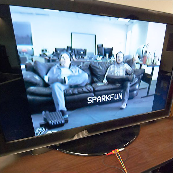
Can we get a screen shot of this thing in action? It looks pretty cool, but what can it do?
Please fix the links to the datasheet and schematic as they point to the DDS chip and board....
Sorry about that. Datasheet link is fixed, schematic will be right tomorrow morning...