- Home
- Breakout Board for AD9835 Signal Generator

Breakout Board for AD9835 Signal Generator
Replacement: None. We do not currently have a replacement for this breakout but a revision is in the works. This page is for reference only.
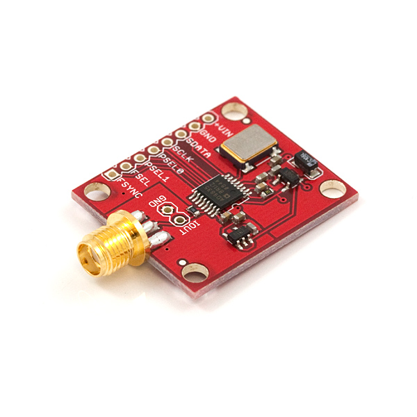
This is a breakout board for the AD9835 signal generator chip from Analog devices. The AD9835 allows the user to make sine waves from 1Hz up to 25MHz with better than 1Hz resolution.
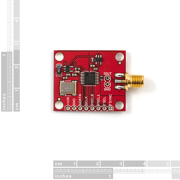
The breakout board has digital and analog supplies with separated ground planes, plus an SMA connector and 2-pin 0.1"-spaced header available for RF output. The output impedance is somewhat high (you can't drive a speaker), so you may want to buffer the signal with an op amp.
**Weight: **0.15 ounces, 4.3 grams
- 10-bit DAC for good accuracy
- 2 frequency registers, plus a register-select
- 4 phase registers, plus 2 register select pins
- SPI communication with a simple command set
- Input voltage 6-9V
- Current consumption 5 to 40mA
- 5V SPI interface
- 1.2"x1.0"
Comments
Looking for answers to technical questions?
We welcome your comments and suggestions below. However, if you are looking for solutions to technical questions please see our Technical Assistance page.
Customer Reviews
No reviews yet.
Need a replacement for this board. maybe with a AD9854
I believe we are working on a new signal generator breakout board, so keep an eye on the new product posts!
Yeah, a AD9854 based one with the option of having an external 10MHz ref clock input would be really useful. I'd like to see the maximum frequency be a minimum of 50MHz, preferably 100MHz.
What voltage regulators are used on the board?
MIC5205
Would love for this to return to the catalog. Any word on a comparable replacement in the works?
I believe we are actually looking into a viable replacement. Hopefully we'll get one on the storefront soon!
When is it going to return the product in catalog?
How do i pump this up to 10V peak to peak? :) Opamp.. and then what?
May I take the eagle files and make my own board? Using batchpcb? If so, why am I getting a drc error where the analog and digital planes meet? Should they be shorted together?
Why is there no longer a function generator kit? Please add that back!!!
We loved that kit too (I was asking around the building for one just the other day). Unfortunately, the chip at the heart of that kit was discontinued by the manufacturer, and without the chip, there's no kit. We're looking hard for a replacement, but so far everything else has been either too expensive or low quality. We're still looking though!
AD's website shows it in production and octopart shows suppliers with inventory... perhaps it was only mostly dead and true love has brought it back to life? Any chance of more?
Sorry for the confusion, the conversation split there. I was referring to our old function generator kit that was based around the Exar XR-2206, which has indeed shuffled off this mortal coil and joined the choir invisible. This breakout board's retirement is a different issue; I believe because its performance wasn't what we had hoped for. I don't believe we have a replacement in development but I will check.
Thanks, I would appreciate it. I haven't found anything similar (programmable from an Arduino).
An Arduino library, or just a little better documentation would be awesome. It looks like the example code in the comments will be useful.
A while ago sparkfun had a function generator kit, I wonder if some of the options in that kit could be adapted for use on this breakout board...
Does anyone know the accuracy of the on-board reference clock? The schematics just list it as a canned oscillator.
In the June 2011 QST magazine, there is an article describing this DDS chip used in a synthesizer for old Ham transmitters. The circuit uses a simple LT1253 amplifier to buffer the DDS output which would be useful to incorporate on this Sparkfun board. He uses a PIC16F877 controller, I would like to know if it is possible to duplicate the circuit and software with an Arduino instead.
There is a file of information at:
http://www.arrl.org/files/file/QST%20Binaries/Jun2011/QS0611Lunsford.zip
but you have to be a member to access.
hi<br />
do we have to put a current to voltage converter at the output or is it built in the circuit
No.. The 300r on the output takes care of the conversion to a voltage for you..
hey<br />
what is the output voltage of this kit??<br />
<br />
<br />
Pretty close to the datasheet spec for the two units I've used.. Which is 1.3V peak to peak, with the bottom of the sine wave at 0V
At high frequencies, (~9MHz) the output looks pretty choppy on the oscilloscope. The frequency is probably still quartz accurate, but if you want something with low phase noise, this might not be a good LO choice.
The AD9835 Breakout Board (just like Analog Devices' own evaluation board for this chip) doesn't have any filtering on its output. This lets you study the chip's output spectrum, and try out filter designs that are optimized for some specific application. It's common to use a low-pass filter with a corner frequency of about 30-40% of the DDS clock frequency, but sometimes you'll do tricky stuff like deliberately filtering out the main output frequency and using one of the image frequencies.
Here are a couple of scope shots that I made. The first shows the unfiltered output of the board programmed for 10 MHz, and the second shows it with a 15 MHz low-pass filter (Mini-Circuits model SLP-15+). The yellow trace is the output signal, and the red trace is an FFT of the output signal.
tek00000.png - unfiltered
tek00001.png - 15 MHz LPF
Looks like you got it working at least - unclear whether it requires only 5V or >6 V because of the on-board regulators. ??
thanks,
Paul
Give it something between 6 and 9V.
Has anyone determined what the impedance is for this device, and any pointers on balancing it to 50 ohms?
The data sheet isn't clear on Zout, but as long as you're feeding it to a high Z input you should be good. If it's full scale drive is 4mA, anything with Zin > 1250 ohms should be fine.
It's 300 ohms I think, so, 6:1 transformer?
Has anybody written Arduino code to control this DDS? It is not as trivial as it seems, apparently. Thanks.
I just got my AD9835 Breakout Board this weekend. I posted a sample sketch in the forum that might be helpful:
http://forum.sparkfun.com/viewtopic.php?f=14&t=20097
Below are the functions I used for to control the output frequency of the AD9835 using my Arduino Uno.
void AD9835write(unsigned long frequency)
{
unsigned long temp = 0;
temp = 0xFFFFFFFF/50000000*frequency;
SPIwrite(0xF8, 0x00);
SPIwrite(0x33, ((temp & 0xFF000000) >> 24));
SPIwrite(0x22, ((temp & 0x00FF0000) >> 16));
SPIwrite(0x31, ((temp & 0x0000FF00) >> 8));
SPIwrite(0x20, ((temp & 0x000000FF)));
SPIwrite(0xC0, 0x00);
}
void SPIwrite(int byte1, int byte2) {
// take the SS pin low to select the chip:
digitalWrite(slaveSelectPin, LOW);
// send in the address and value via SPI:
SPI.transfer(byte1);
SPI.transfer(byte2);
// take the SS pin high to de-select the chip:
digitalWrite(slaveSelectPin,HIGH);
}
@tjfreebo - what is your pinout for the AD9835 -> Uno ?
cheers
My pinout for the AD9835 -> Uno was: SDATA -> Pin11, SCLCK -> Pin13, PSEL0 -> GND, PSEL1 -> GND, FSEL -> GND, FSYNC -> Pin10
Does this come with the required reference clock? Thanks.
The onboard reference clock supplied to the MCLK pin on this breakout board is 50MHz.