- Home
- Product Categories
- Wireless and IoT
- Venus GPS Logger with SMA Connector

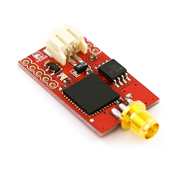
Venus GPS Logger with SMA Connector
Replacement:GPS-10920. The new version of this board is built with the Venus638FLPx-L, a more robust drop-in replacement for the Venus634LPx. This page is for reference only.
This is one of the smallest and most powerful GPS loggers on the market. The Venus GPS module can be configured to an amazingly powerful 10Hz update rate, with 14 channel tracking and can store up to 32Mbits of GPS data! Boasting 28mA operating current, and high sensitivity, this receiver seriously opens new doors for tracking. Module outputs the standard NMEA-0183 or SkyTraq Binary sentences at a default rate of 9600bps (adjustable to 115200bps).
The Venus634LPx has improved sensitivity, an integrated LNA (with multipath detection and suppression), built-in RTC, and integrated single power supply making it very simple to use. In addition, the module supports data logging with an external SPI Flash!
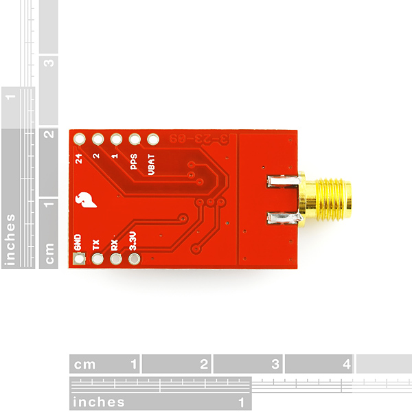
The logger's SPI Flash can be configured over the TX and RX pins using our USB to Serial FT232 Breakout Board.
Check out our GPS buying guide!
- 51 channel acquisition and 14 channel tracking
- SkyTraq based chipset
- 10Hz max update rate (1Hz default)
- Integrated LNA
- Single 2.7-3.3V supply
- 3.3V TTL UART
- 32Mbits of flash space
- Power: 28mA tracking
- Sensitivity: -161dBm
- Accuracy: <2.5m
- Hot start: 1 Seconds
- Cold Start: 29 Seconds
- Supports active or passive antennas
- Supports SBAS (WAAS, EGNOS, MSAS)
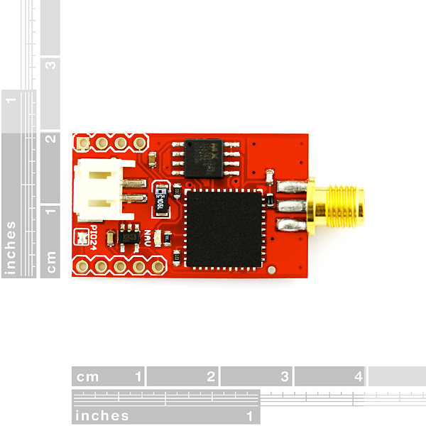
- 1.25 x 0.75 inches
- Schematic
- Venus634FLPx Dataheet
- Binary Command Set
- [GPS Viewer Software](http://www.sparkfun.com/datasheets/GPS/GPS Viewer_1124.zip)
- Datalogging Datasheet
- Design Guidelines
- Reference Layout
- Layout Guidelines
- Firmware Update
Comments
Looking for answers to technical questions?
We welcome your comments and suggestions below. However, if you are looking for solutions to technical questions please see our Technical Assistance page.
Customer Reviews
No reviews yet.
One problem/correction (please fix if you redo the board). I said it fits into a socket. Not quite. Nearly every other BOB I have is the same width - I'm using arduino pro-minis and this is a bit thick.
It is slightly wider than everything else though you can plug it into a standard .1 spacing socket, but the connections will be bent inward.
This is visible if you look closely in the photograph but is not really mentioned.
So it works, but I will probably go with the non-logging.
Yes, I've noticed this too. And it is a problem that I hope gets fixed. The non-logging version doesn't have this problem.
Is there a version 2 planned for this board (and GPS-09133) that does not have the VBAT tied to 3.3V? It looks to me like both boards have pin 18 and pin 36 tied together under the chip where I can't get to it to cut the trace.
Yes, the next version will have VBAT connected to 3.3V through a jumper. For now, the VBAT pin is non-functional. Thanks for letting us know and sorry about that.
Rather than just a jumper, I'd recommend a diode and series resistor between 3v3 and VBatt, maybe even a footprint on the bottom for an SMD supercap (VBatt to gnd). Although I haven't tested it (yet), a small supercap should keep VBatt above VBatt(min) (1.5V) for more than the 2 hours before a coldstart is done by the chip regardless.
Meantime, the connection between 3v3 and VBatt CAN be cut on this board. It is not connected under the chip.
This is a great GPS and the logger function works well.
The supplied software works well although even with the baudrate at 115200, the sw can't keep up at 10Hz update rate. (at least not on my pc!)
Time to first fix is snappy and as advertised, it even has no trouble acquiring indoors! (+26db active antenna)
jsampson is right. Vbat and 3.3V (pin 18 and 2) are tied together so be carefull! do not hook up anything other than 3.3V!!! They shouldn't have made a Vbat pin if they were going to connect them.
Also the default rate is 9600bps Thats what my
Venus chip's default is and that's what is on the datasheet pg2.
can the Venus data logger be used as a standard gps board (e.g. the GPS-90133) as well?
Thanks!
This was asked a while ago but I also needed to know the input voltage range. It looks like the regulator is a Micrel part with an input voltage range from 3.5V to 16V for the 3.3V part.
Can I argue that the datasheet says 2.5V to 16V in? Not 3.5V to 16V...
I'd love to hear someone confirm that you can feed higher volate into this board - I have an automotive application, and would like to bypass the process of separately regulating 12V down to 3.3V for this. I can just provide a 12V input to this board if I apply it at the battery connector, and not the other 3.3V labeled hole, correct? Anyone able to confirm?
Yes, you can do this. The voltage regulator does have an upper limit of 16V, and it is likely to get warm at 12V, but it will work. Do apply 12V to the battery connector, but do NOT apply 12V to any other pins (the VBAT pin is for a low-voltage battery backup input, not a power input).
Sold. Thanks, Mike!
Hello, I cannot successfully track my position. I have been sitting outside for more than 20 minutes with the GPS connected to my computer via the FT232. I am using GPS-00177 antenna and I also use lipo battery to power the GPS..
Please forgive my extreme ignorance. I'm new to electronics/microcontrollers and I've not previously worked with GPS. Googling hasn't helped (tried to RTFM). So... could someone tell me how to connect this thing to an Arduino? I'm not asking for a sketch. Rather, which pins do I use? I'm only interested in the GPS/NEMA data (i.e., not data logging). I just need a wee push to get me started. I need to get to the point where I can fumble with and curse at the data/etc. Programming tends to be the easy part of all of this stuff. Physical connections/etc are the hard part. Help!
+3.3v to the 3.3v power supply, GND to ground, GPS Tx to the Arduino Rx pin, and GPS Rx to the Arduino Tx pin. If you have just bought it, you need to set your microcontrollers UART to have a Baud rate of 9600, and bobs your uncle, you should be able to recieve data.
Thank you, TCWORLD! With your guidance, I was able to get up & running in twenty minutes (unfortunately, I'm still a bit thick). For the sake of helping others that are a little intimidated/lost, I'm posting the sketch that I used on the Arduino Uno to start seeing the NMEA data. Oh, PLEASE NOTE that I connected to digital pins 2 & 3. That is, TX from the Venus GPS goes to Arduino D2, RX to D3.
include
int rxPin = 2;
int txPin = 3;
NewSoftSerial gpsSerial = NewSoftSerial(rxPin, txPin);
void setup()
{
pinMode(rxPin, INPUT);
pinMode(txPin, OUTPUT);
Serial.begin(9600);
gpsSerial.begin(9600);
}
void loop()
{
char c;
while (gpsSerial.available())
{
c = gpsSerial.read();
Serial.print(c);
}
}
This isn't the terribly useful... but might help someone else feel less like crushing the thing with a brick. NewSoftSerial is available here: http://arduiniana.org/libraries/newsoftserial/
Thank Uncle Bob for me, too.
Just wanted to let you know that I used your code to get my gps up an running and am very happy. It took it a minute to acquire satellites and then the data was flowing.
This is great example code and a good starting place for this gps.
Thank you.
http://cid-478828d520112340.office.live.com/self.aspx/.Public/STI%5E_01.04.48-01.10.29%5E_npse%5E_VENUS634.zip
Here's the latest firmware for the Venus 634
I seem to be having trouble with this unit acquiring satellites. The unit can pretty routinely connect to one or two satellites but without lock (a hollow red bar on the GPS viewer). I drove around for maybe 20 minutes last night trying to get it to see more satellites to no avail. Then, seemingly at random, it picked up tons of them and immediately locked. I could then cold start in a matter of a few seconds (5-10). This worked all last night.
However, this morning I am back to the exact same problem I started with last night. No lock. The antenna is in the exact same spot that worked well last night. Any ideas on what could be causing these problems?
I am using this antenna: http://www.sparkfun.com/products/464
Also, what are pins 1,2,20 for?
All GPS receivers need to have ephemeris data to know where the satellites are. This is transmitted by the GPS satellites themselves, but takes about 30 seconds and a good signal. The alternative is A-GPS, where the data is downloaded from the internet. In either case, the ephemeris is then valid for four hours.
It sounds like your module had trouble receiving the ephemeris. Did the antenna have a clear view of the sky? When you "drove around", were you driving in and out of cover? It's best to stay still while the receiver is downloading the ephemeris, otherwise it can be interrupted and it might have to start again. Once it has the ephemeris it knows where the satellites are and can make much better decisions about where to get data from.
Pins "1", "2", and "24" are GPIO pins from the Venus chip. The datasheet says GPIO24 is used on power-up to select between two different acquisition modes. You might want to investigate this.
Hi there, would it be possible to interface this board with the uberboard or the logomatic?
Thks
JA
What is the input range for the voltage regulator? It'd be nice to be able to connect it directly to a LiPo battery.
Another question... has anyone tried logging to flash at 10hz?
Ok. Got it working. TX-I (on the gps chip) => Rx (on the usb breakout board) and TX-0 => rx. Gnd to Grn and 3.3v to 3.3v of course.
Hi. I connected this chip via the breakthrough board to my laptop. the led lights up and stays on. I cannot connect to this device in GpsViewer. I saw t flashing at some time but now it just stays on. I changed TX-RX pins on the USB board. no change. by the way, which rx-tx pins to use on the breakthrough board? there are 2 rx/tx pins. RX-I/TX-0. RX-D/TX-D???
Thanks.
Is there any way to send a command over the serial connection to this VenusGPS to change the baud rate or the NEMA string selections WITHOUT using the GPSView software.
I have it working on an Arduino board. The sensitivity does not seem quite as advertised, but it more or less works. But I need to bump it up from the default 9600 bps and cut out a couple of the unnecessary NEMA strings.
What commands do I need to send it? I don't see them documented anywhere.
Jack Rickard
http://www.sparkfun.com/datasheets/GPS/Modules/AN0003_v1.4.8.pdf
Found it. This gives the binary command set.
In Arduinospeak
int baud38400 (160,161,0,4,5,0,3,1,9,13,10,0);
Serial2.write(baud38400, 11);
This will write the string for setting baud rate to 38,400 and save it to both SRAM and FLASH.
This GPS is very simple to use. If you only want to use it with SkyTraq software, you only have to connect tx and rx pins to rx and tx pins in the FTDI USB board and connect a 3.3V source. I couldn't use the 3.3V of the FTDI USB (maybe because the current wasn't enought due to the extension USB cable). Most of the problems with this GPS are related with not providing enough current, although the voltage is right, so be carefull with this. Once connected to the SkyTraq, you'll see something like this, after some time tracking satellites: http://img138.imageshack.us/img138/2058/gpsv.jpg
I have to say that although I bought two of these GPS, one of them didn't work properly. One of them connects almost inmediately, but the other only achieves to track one satellite with very few power and that after a long time, and never get the 3D position. I think it's a problem of the sensibility of the GPS chip.
hi, i tried to send binary commands to my venus gps, but i did,t receive any answer. I simply connected the gps to the serial-usb coverter and to the antenna. What type of connection i have to do? Can you help me to send commands to gps? thank you very much.
Where can I get the GPSVIEWER program. I tried to click on the link for this page but the zip is corrupt or something.
Hi everyone...just bought this device but I cant make it work, I'm new at working with gps devices so am asking for your help. How should we connect this stuff??, is it correct to use a max232 to comunicate it with the computer?...thanks!
I use the 3.3v FTDI breakout sold here.
It provides power and had txo and rxi which go to the rx and tx on this board.
so, you dont believe that using it with a max 232 will work?...
Please ignore my previous post. It's up and running now. One more thing I see is that it's not as sensitive as Sparkfun LS20031 module (although it should be better from spec). I'm using it with Sparkfun antenna GPS-00177 and it takes up to 5 minutes to lock (indoor, through wooden ceiling) while LS20031 takes much less time (~3 minutes). I will check with outdoor performance tomorrow. Does anyone ever compare these two modules? Thanks all!
I connect this to a 3.3V power source that shows the module is taking 30mA. The antenna is Sparkfun GPS-00177
Both Rx and Tx are at HIGH (3.3V). No data!
Does anyone know why ? Thanks!
Is this the correct antenna for it?
http://www.sparkfun.com/commerce/product_info.php?products_id=177
I recently brought this GPS and also bought that antenna, both have been working great for me.
Working well, through a Parani BT unit ( http://www.sena.com/products/industrial_bluetooth/esd.php - the smaller 200 unit which has the same width spacing and also uses 3.3v - 4 wires across after configuring the same baud rates on both and everything works).
It would help if I could confirm the PPS (which edge?) is at the UTC second interval accurate to N microseconds, and/or the relationship between the time reported (it reports down to the millisecond) of the NMEA sentences and the time it means? The start bit of the $ character in the GPRMC sentence? Some other character?
My other 10Hz gps (gblox based wintec - can't do 10hz waas) 99.9% of the time reports with zeros for the tens and ones milliseconds.
This information has to be somewhere but I can't find it.
To ask again (other than something to do with a different ROM version), what are the GPIO pins for?
I had this little guy up and running in minutes, I used the GPS-00177 antenna with built in LNA. This unit even picks up satellites on my workbench inside. The data sheet specifies a power save mode but does not go into detail. Does anyone know about this power save mode? the default baud rate is 9600 but if you want to download the log files you need to change to 115200. I down loaded my log file and decompressed it to kml and it looks great in Google earth but I need the track to show date and time. I am communicating to the device using xbee's so I can put the unit outside and test features, I wan't to install it into the car to log where it's been.
How did you decompress it to google earth? when i try to download, i get a file called data.log - which when opened in Notepad is just a load of ? signs. If i try to click the compress button in the software, it starts to make a kml, but then just crashes. Any ideas?
If I read the Datalogging Datasheet correctly, the logging can be performed at a maximum rate of 1Hz, so if you want to log at 10Hz, you'll have to hook the device to a computer and log the data there. If that's the case, you may want to consider the GPS-09133, which is this same receiver without the flash memory.
I set mine to an update rate of 5Hz, set Tmin to 0 and it DOES in fact log at 5Hz. The recorded time resolution is only 1 second, but there are 5 records with the same timestamp. I'm pretty sure 10Hz will work.
I have following problem:
I set the update rate to 5Hz (SRAM + Flash -> bad idea) and now I am not able to send any commands (beside hot and warm start)
Baudrate is at 38400, receiving data (as before) over FTDI Basic. Error message: Timeout: GPS device no response.
Any suggestion how to set the update rate back or to be able again to communicate with the gps?
thanks in advance!
MCX/MMCX instead of SMA would be nice for future versions.
What are the GPIO 1 and 2 pins for?