- Home
- Product Categories
- Kits
- ClockIt

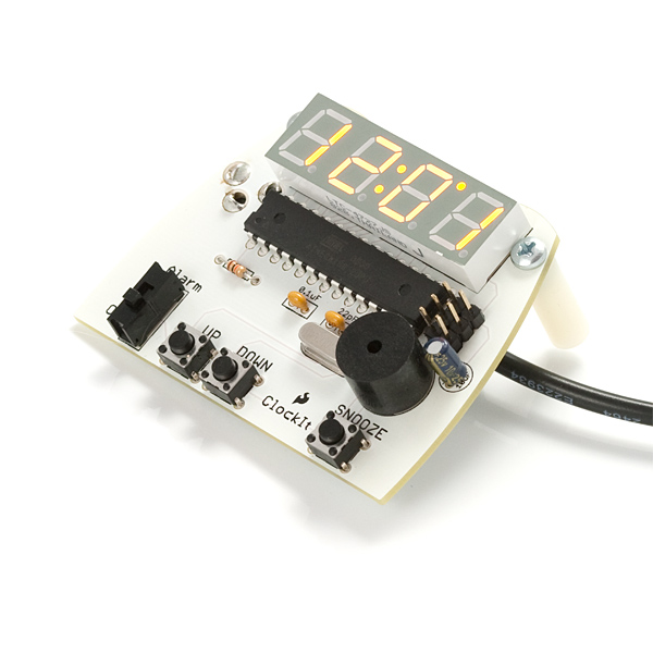
ClockIt
Replacement:KIT-10013. The new revision uses a different brand of display and some adjustments were made to accommodate the new part. This page is for reference only.
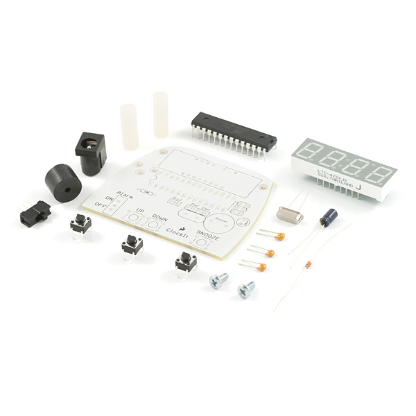
This is a great kit to learn the basics of soldering. ClockIt is a basic alarm clock with buzzer based on the ever popular ATMega168. If you're just learning how to solder, this kit should take you 15-20 minutes. If you're a weathered pro at soldering, this is a great relaxing build that should take 5-10 minutes.
No programmer required. The ATmega comes with firmware installed!
Open Source Hardware: We like to share. The original engineering files are available for mass hackery.
- Eagle Files (Licensed under CC v3.0 Share-Alike)
- Schematic
- Source Code
- Assembly Instructions
- Improved Source Code Forum Post
- MakerBot Mounting Brackets
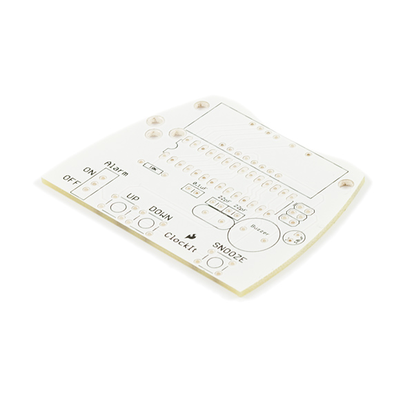
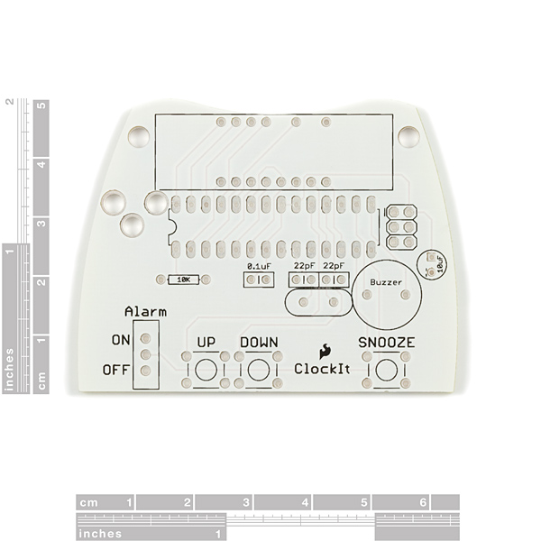
- 1 x ClockIt PCB
- 1 x ATmega168 (pre-programmed)
- 1 x 4-digit display
- 1 x buzzer
- 1 x 10uF cap
- 1 x 0.1uF cap
- 2 x 22pF caps
- 1 x 10k resistor
- 1 x 16MHz crystal
- 1 x barrel jack
- 1 x mini power switch
- 3 x push button reset switches
- 2 x Screws
- 2 x Plastic Standoffs
- 1 x 5V wall wart
- Time (AM/PM)
- Alarm (On/Off)
- Snooze (alarm resumes after a 9 minute snooze)
Comments
Looking for answers to technical questions?
We welcome your comments and suggestions below. However, if you are looking for solutions to technical questions please see our Technical Assistance page.
Customer Reviews
No reviews yet.
I'm no electrical engineer so this will appear as a rather dumb question here but how tough would it be to replace the buzzer with a light? I'm thinking this would be good to put in the kids room (ages 2 & 4) and then teach them that they can't get out of bed until the light comes on. (In case you don't know kids sometimes get up at 4 or 5 AM and want to play.) The light would have to stay on for about an hour or so. Running it off of a 9 volt or 2 AA's would be better as well since you don't really want too many things plugged in in a room like that. Make it and you will sell a million of them!
If you teach your kids that, be sure to add "unless there's a fire"
Instead of replacing the buzzer, you could just have the display flash or make a funky animation that is displayed instead of the time.
You -could- go one step further, and have the clock unlock the door only after the alarm goes off.
I am kidding, of course... >:-)
Really great idea! I would love to see that mod if you get the chance to try it.
All the battery operated clocks I've seen use an LCD display for lower power consumption (passive black and gray LCD like on a sports watch). Because of the bright LED display, the ClockIt uses enough power that it would kill the batteries within a few days.
Great idea and price! The clock idea leaves the "student" with something they can use. The basic platform could probably be re-purposed to something else useful when they want to practice programing. It even comes with a 5V wall wart!
Thanks! We worked hard to try to hammer down the price.
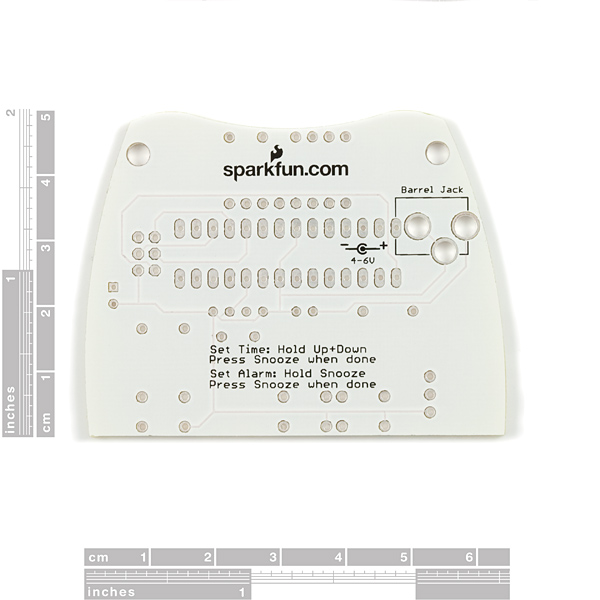
How do you set the time on this clockit kit?
thank you! marC:)
Oh, and of course, make sure this is the kit you're asking about :) Although the interface doesn't seem to have changed, this particular iteration was replaced... and its replacement was also replaced. At the current time of writing, the ClocKit is: https://www.sparkfun.com/products/10930
It depends on the firmware. Stock firmware (if I'm reading it right):
But how is it controlled? wouldn't the 328 not have enough pins to individually control each LED? I realize not all would ever need to be lit up, but it needs to be controlled for 18:88 - that's a total of 26 leds! Is it a serial 4 digit display?
They multiplex the wires.
If you want to display 12:34
first you send a "1" to the display. Every digit is now a "1", but if you only light the first one, you only see one 1. Then you turn the first digit off, and send a 2, light up the second digit, then turn the second digit off and so on. This happens really fast so you eye sees all four digits lit at once but in reality it's only one at a time. Have a look at the schematic. You have four wires for the digits, and 7 wires for the segments. 28 led's with only 11 wires.
Oh, multiplexing... I didn't think of that - thanks!
Fun little kit! Keeps time pretty much spot on, and was easy enough to put together. That said, I did have a few issues with the instructions though.
1) The polarity for the electrolytic capacitor wasn't printed on the board I received. I was able to figure it out (it hasn't blown up yet!) by looking at the picture in the instructions and tracing the circuit, but for a beginning kit you may want to make sure this is clearly marked.
2) Same issue as above with the buzzer. Silk screen doesn't have polarity marking. I figured it wouldn't matter much for the speaker, but just a heads up.
All-in-all, a really nice and quick-to-build kit. Now, I'm off to build a cool enclosure.
Umm, I'm pretty sure I was given a blank 328, I'll try and see whats on it, but it was either not programmed or dead!
Keep tech support updated with what you find.
can someone explain me how to hit the clock?
grateful
Thanks
So I built this kit as my first foray in to soldering. I am pretty sure I got everything right, except for the fact that I did evil things to the 10uF cap. I went to my neighborhood Radio Shack to pick up a replacement, but realized I really didn't know what exactly I should get. I was hoping for a point in the right direction on what part I should look for.
Standard 10uF @ 16v+ radial electrolytic capacitor. Its just a decoupling capacitor so it will function without it. It wont be happy though, and might act out in anger...
Here is a neat example for enclosures:
http://gallery.me.com/fifteen54/100054
The box itself is made by "@ the Office" which is a Walmart brand of stationary and office supplies. I can't seem to find these on the web anywhere, but should be in your local Wally-World. The clock is a near perfect fit. I had to shave roughly .125'' on either side of the PCB, but other than that it couldn't have been planned better. With a Dremel by your side it's too easy. It is a bit on the light side so I counter weighted the bottom with BB's and a heavy dose of hot glue. The back of the box is magnetic so you could toss in a L4931CZ50-AP in conjunction with a 10uF and a trusty 9v to create an alarm clock for your mini-fridge door....
The clock kit is a fantastic deal. It keeps accurate time. I made a bracket and mounted it vertically on a small wooden base.
We've just assembled our first ClockIt and have some issues with the design & instructions.
The major issue: the ClockIt display flickers noticeably at somewhere between 20 and 60 Hz. I hope this could be fixed in software.
Hardware & instructions issues:
We couldn't find the gold '-' sign on any capacitors; our kit came with a grey '-' sign. The instructions didn't make it very clear that each part should be soldered down in the order given. It also would have been easier to trim the legs on the ATmega168 before soldering it down. Actually, it was awkward that the barrel jack sits atop the ATmega168's pins. The board is much prettier on the top than on the bottom.
Lastly, we had trouble keeping the display flush with the board. Perhaps it should be soldered down second rather than 10th?
is this compatible with COM-09481? The yellow leds look cool, but can the blue led display work with this?
wrxstiv8:
Not sure if you contacted tech support and got a reply already (comment almost 3 months old), but the simple answer would seem to be "no".
The YSD-439AxxX-35 series (COM-09480 .. COM-09483) are Common Anode. The LTC-4727JS that appears to be used in the ClockIt as shown in the pictures is Common Cathode.
Presuming this hasn't changed -but- you can find a way to flip the CC logic to CA logic, then the two components are actually very similar. The only difference seems to be in how L1 and L2 (the colon), and L3 (the top dot) are handled.
In the LTC, L1 and L2 are individually adressable (pin 14 and pin 16 respectively), while in the YSD they are hardwired in parallel (to pin 12, which doesn't exist on the LTC).
L1 and L2 being separate on the LTC is a non-issue with the default firmware as they blink together anyway, so pin 12 from the YSD could be wired to either pad 14 or pad 16.
In the LTC, L3 shares its common cathode with L1 and L2 (on pin 4) and anode shared with 'segment C' (pin 13), while in the YSD L3 it is hooked up to a separate anode (pin 10 - doesn't exist on LTC) and cathode (pin 9 - exists but isn't wired on LTC).
This is also easily fixed - pin 10 would get wired to pad 4, and pin 9 would get wired to pad 13.
Pins 10 and 12 would also have to get bent inward for this, or you'd have to drill some holes into the ClockIt PCB to facilitate them.
( Just to re-iterate: wiring pin X to pad Y does presume you have the CC vs CA issue resolved )
Even with all that, though, you'd probably end up disappointed with the brightness of the display, if it lights up at all; the Vf of the 'blue' (cyan) YSD is 3.4V, while the LTC is 2.05V (similar to the 2.1V used by the red, yellow and 'kelly green' (lime) YSDs. So you'd have to adjust the board/firmware for that as well.
All in all, presuming it's still using the LiteOn LTC part, you'd be better off finding replacements from LiteOn (though I only see red and yellow), or other manufacturers that use CC (typically missing LD3, but for the purposes of the default ClockIt, you could use another decimal point).
Or go crazy and pick up individual blue 7-seg displays and a piece of protoboard and wire them up to some header pins, matching the LTC-4727JS. Given these displays are typically mounted behind a filter plexi window, you wouldn't even typically notice.
Tip: turn the first and third digits up-side-down. This puts a decimal point in the top-left corner to use as an AM/PM indicator, two decimal points 'above each other' for the colon (a bit widely spaced vertically, of course), and leaves one decimal point in the bottom-right corner for alarm on/off indication, without needing to look specifically for left-hand/both-hand decimal point parts. I actually prefer this layout and is how I'll setting mine up as I want bigger digits that I can mount vertically anyway.
Please direct technical questions to techsupport@sparkfun.com.
Hmmm, mine included 1 pushbutton and 3 slide switches....
My guess is that with a 28 pin ZIF socket there would be nothing stopping you from putting an Arduino bootloaded ATMega168 in the place of this pre-programmed chip. Just get 2 ZIFs and put on on the Arduino for programming purposes, then slap it in this thing.
Does the programmed ATMega have the Arduino bootloader on it as well as the clock code? or is a programmer completely necessary?
It would be a lot easier to mount this if the Display were on one side of the board and the rest of the components on the other side. Also, real pushbuttons, either panel mount or PCB mound would be better.
I never have understood why most clock kits are like this. All the components on the same side of the board :-(
Kenny
Is this board designed to fit in the Clear SparkFun project case (Stock No. WIG-08632)?
I've been trying to disect the source code of this project. (You know...learning and stuff...) The pin connections on the schematic don't seem to match the pin selections in the source code...Either that or I'm confused... no, no, it must be the schematic.
Any thoughts there?
This would be an amazingly handy device if it had perhaps 10 alarms. It could be used around the house for kid prompting(wake,breakfast,bustop)or in schools (end of class, end of lunch), who knows where else.
I'm actually using this kit as the basis for a cleanup bell for the technology lab at my school. What I'm planning to do is hook up a relay instead of a buzzer, and a siren will be hooked up to the relay. The code will need to be changed to create multiple alarm times, and also to simply apply a digital high to one of the buzzer pins and a low to the other, instead of an analog write.
This could be a cheaper alternative for me to replicate your huge wall-mounted clock. With the code being open source, it would probably be possible to have the clock set from a GPS too :)
Amazing! But, you mentioned that it's possible to hook up a LCD to it. Can you go into detail how to do so?
Any chance of a fitted enclosure being offered?
The picture of the assembled device seems to have a nice mounting point for programming the chip, but in the parts list and in the picture of all the parts I do not see that part. In the schematic I believe this is the AVR_PRG part.
This looks like a nice kit and all, but won't we need something to connect to the AVR to program it? Perhaps you should mention that or have a link to the things you will need to actually program the chip.
Though you'd still need a programmer if you wanted to reprogram the Mega, I don't generally solder headers onto my projects anyway. Instead, I keep the header plugged into my programmer. Slide the other end of the pins into the holes on the board where you wouldhave* soldered the header, torque it a little to one side, and you're good to program.
... Hopefully somebody will correct me if that doesn't carry over to this board, which seems to be a little more whitewashed than I'm used to.
You're correct, you can program the device using the method you've described. In fact, that's how we program many of our boards in-house.
The ATmega comes pre-programmed. You just have to solder the clock together, plug it in, and it works!
I apologize - the pictures are a bit off. We do not include the ISP 6 pin header. But you will not need a programmer.
You are correct - if you want to change the code, you will need to solder in a header and connect a programmer.