- Home
- uLog - The Lil'est Logger

uLog - The Lil'est Logger
Replacement: None. We are no longer carrying the uLog in our catalog. This page is for reference only.
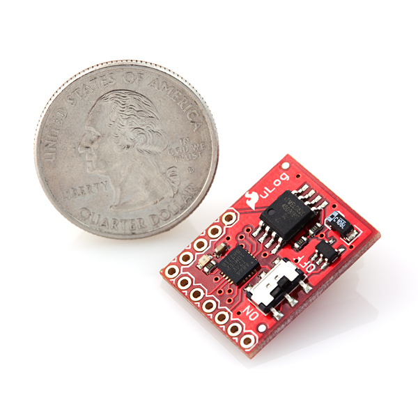
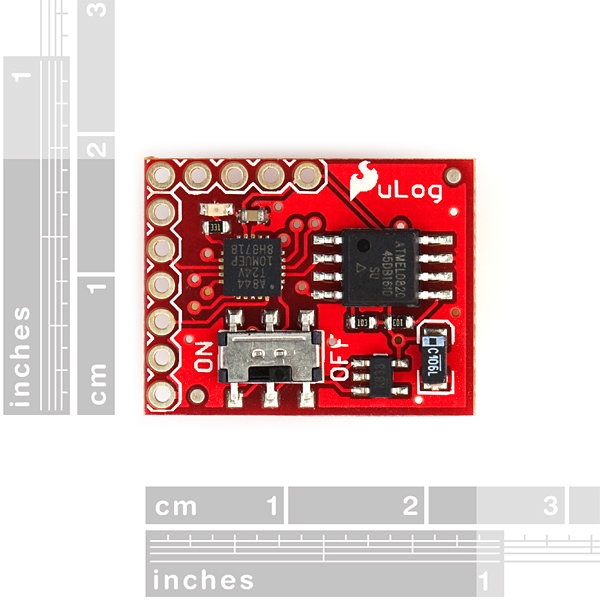
The uLog is a tiny analog datalogger. Central to the logger is an ATtiny24 mated with an AT45DB161D 16Mbit flash IC. Sampling at 50Hz, it’ll log 3 channels of 10-bit ADC for about 2 hours before the memory fills up.
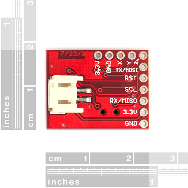
Very stripped down and simple to use: at power up it determines if a UART line is attached. If there is, it spits out a “?” and waits for user input. There are only 2 commands: “r” for read and “e” for erase. Erasing the flash sets all addresses to 0xFFFF, and reading dumps all the data up to the first 0xFFFF. If there’s no UART line attached it starts sampling. If connecting with one of our FT232 breakout boards, all you need is TX, RX and ground. If using an RS232 shifter board you will also need to connect 3.3V.
The power input is a 2-pin JST connector, which works well with our LiPo batteries, especially the small 100mAh LiPo, and it draws just 4mA with an ADXL320 MEMS accelerometer attached. An ON/OFF switch is also included.
There are so many uses for this device! We strapped it to a rocket while it logged the analog output of an ADXL321 accelerometer.
- AT45DB161D provides 16 Mbits of flash
- Up to 3-channel ADC logging
- Access to ATtiny24 SPI pins
- Simple-to-use UART (38400 baud) interface for reading and erasing flash* Size: 0.9x0.7"
- Weight: 8.07g
uLog - The Lil'est Logger Product Help and Resources
Core Skill: Soldering
This skill defines how difficult the soldering is on a particular product. It might be a couple simple solder joints, or require special reflow tools.
Skill Level: Noob - Some basic soldering is required, but it is limited to a just a few pins, basic through-hole soldering, and couple (if any) polarized components. A basic soldering iron is all you should need.
See all skill levels
Core Skill: Programming
If a board needs code or communicates somehow, you're going to need to know how to program or interface with it. The programming skill is all about communication and code.
Skill Level: Competent - The toolchain for programming is a bit more complex and will examples may not be explicitly provided for you. You will be required to have a fundamental knowledge of programming and be required to provide your own code. You may need to modify existing libraries or code to work with your specific hardware. Sensor and hardware interfaces will be SPI or I2C.
See all skill levels
Core Skill: Electrical Prototyping
If it requires power, you need to know how much, what all the pins do, and how to hook it up. You may need to reference datasheets, schematics, and know the ins and outs of electronics.
Skill Level: Noob - You don't need to reference a datasheet, but you will need to know basic power requirements.
See all skill levels
Comments
Looking for answers to technical questions?
We welcome your comments and suggestions below. However, if you are looking for solutions to technical questions please see our Technical Assistance page.
Customer Reviews
No reviews yet.
Sorry if this is a very obvious question, but how do I get data off of this? I have followed the online tutorials for how to wire the FTDI connector to the uLog, and I have verified I have it hooked up properly. Using the terminal in my mac, I can see the serial port but when I try to access it, it says "Access Denied".
What is the simplest way to "send 'r' over serial" to get my data? I have access to both a windows and a mac, but can't get either functioning.
Heads up, the clocks on these vary by a few percent, so if you are going to gang up multiple loggers the data will be a little out of sync. Mine were off about 2.7%
Hi!
Can you please provide the PCB layout files for uLog?
cheers!
Email us at techsupport@sparkfun.com and we can provide the eagle files. Thanks!
A very basic way to pull data off is to use Hyperterminal. Connect to the Ulog, for example, using a FT232 board and a USB cable. If you type 'r' in HT, then the Ulog will spit out everything that's on it in hexadecimal format (I believe...).
I think you have got the weight of this wrong, even with the power connector installed, it should not be more than 2grams.
if you add the battery then 8 grmans is ok but not without the battery
Can I get one of these? I'm looking for something really small that can sit there and read sensors values. It is shoe mounted so it has to be small.
the link to the tut is dead - any replacement?
It looks like they might be having issues on the server side of things with the website. Hopefully it will be back up soon.
By modifying code, Is it possible to sample at 1500hz on single channel ? When other channels are disabled.
I have the same question as dtderry.
Do I understand correctly that the power input is regulated by a Micrel MIC5205 or equivalent, and so it can use from 2.5V to 16V power source?
Sparkfun team: Can you put the uLog code up on Github officially so we can improve it? I've got a lot of ideas, and this seems to be your only logging board that has a built in ADC and memory, and can log at high Hz.
I want to improve it so we can control better how and when it logs, and maybe even make it play back. It strikes me that this could be kinda useful for audio...
uLog hack with code: http://forum.sparkfun.com/viewtopic.php?f=14&t=31194
What's the license on the source code? There's none specified here on the product page, and there's none in the ZIP file with the code.
How is the data from the 10-bit ADC formatted when it is dumped, comma delimited?
Hi
Since I can't find 16g analog accelerometers on your site, is it possible to modify this to use log I2C data? and if so can any one give a pointer or two?
Yours Simon M.
0x3A28213A
0x6339392C
0x7363682E
hi all,
does anyone have a solution or example code for 1 channel and bigger sampling
thanks in advance
I changed the code to log at 5Hz (but I can show you how to set it to any frequency), would that help? Let me know and I can send it to you.
I am having similar issues with the provided code not producing the correct baud rate. I'm also trying to log at 2Hz although 5Hz would work. If you could send me your working code it would be extremely appreciated.
I put up the code (main.c) and the Makefile on: https://docs.google.com/#folders/folder.0.0B5ay9K0LURz6YTFiOTY1MDItNTcyNS00YWNlLTlmNWEtZDc2MzVmMTQzZDlm
and also an explanation of what I did with it:
http://openbiologger.blogspot.com/2011/06/5-programming-miniature-accelerometer.html (see section Set up the Program)
I think you should get 2Hz if you change
if (Elapsedcount>=4)
to 10 on line 71.
Also I decided to make the uLog status LED blink five times during logging and then stop blinking after that to save battery. If you don't want this you should be able to just delete the variable LEDcount on line 58 and also delete the if statement that starts on line 486 and all the lines involving LEDcount within that loop. If you set the logging frequency to be slower than 50Hz, the LED blinking frequency will also drop. For 5Hz, I get one blink every 20 seconds or so.
I hope that helps!
Thanks! It works perfectly now. You saved me hours of debugging with an O-scope.
It seems that the AT45DB321D 32mbit flash is pin compatible.
Does anyone see any issues in modifying the firmware to use this part instead?
Thanks!
For info: It seems the provided source does NOT match what is flashed in the current batch of uLogs. I.e, the device works fine if you use it as is, but just recompiling the provided source and flashing the logger gives faulty operation. Logging works, but readback doesn't, so it's mess if we want to change something in the code as we don't have a working starting point, and firstly have to debug code that should work in the first place before being able to work...
I checked the serial signal with my new Logger and found that for some reason the baudrate (defined by bitwidth) was too far off the 38400 mark (about 37000), so even if the logger actually sent the correct data, the receiving device wouldn't receive it properly. A device with originally loaded firmware yielded about 39000bps, which is closer, and gives proper operation.
To solve this, replace delay_us(24); by delay_us(23); in getc() and putchr(), and delay_us(36); by delay_us(35); in getc().
Apparently sparkfun "corrected" this for production, but didn't update the source file on this page.
Hey,
Thanks for that!! Saved me a ton of trouble.
Need help with this product, I can't seem to communicate with it.
I've hooked up and oscillosopce and am monitoring the rx pin for any transitions. I've connected the bus pirate and made sure that the TX line is high. I've gone through the code and found
//If there's a high-ish voltage on the MISO line,
//we're likely connected to a serial link
I see nothing, but the LED is blinking every second or so. Is there any documentation for this thing? How do I know if it's broken? I get no output from the RX line at all. Can I return it and get another one?
I went ahead and sent the product back to Sparkfun, it was defective and I received a return. Once I got the new one, it worked fine. As for getting it to work with the bus pirate, it works for basic bring up, but if you want to read from it, good luck. The bus pirate can't keep up and drops characters. I suggest getting the FTDI basic 3.3V to communicate with this little gadget.
When it flashes every second, it's currently logging. To communicate you need to power it off, connect the serial port to a computer for example, and power on. It will detect it's connected and go into command mode. A high impedance connection like a scope won't be detected.
Has anyone every got this thing to communicate with the bus pirate? I'm having trouble getting it do what I want. It looks like it is drawing power through the pull-up on the tx pins. I don't even have a battery connected. Any suggestions?
Only a few years late but it gave me issue until I realized I was using Open Drain output type in the UART config! The following steps should work:
At this time the uLog should print a '?' on screen. Type 'r' to dump the memory to screen, 'e' to erase it.
If I could change the hardware, I'd also make these changes:
* 5V for AVR, 3.3V for flash chip. This way, it'd work with all AVR programmers, and could record input from normal 5v circuits without external voltage dividers.
* Onboard voltage divider network (6 resistors and a 3-DIP switch?), for recording inputs above the ADC voltage.
* A more compatible power plug!
* I don't care much about this, but an external 12.8mhz oscillator would allow the ADC to run at its recommended maximum rate (200khz), for the highest possible sampling rate.
there is a problem with having the flash chip running at 3.3v and the microcontroller at 5v you would have to add a a voltage translator chip or a voltage divider between every single pin connected between the devices, otherwise you could destroy the flash chip.
Another issue with having this board run at 5v is that to run off a single LiPo cell it would require a voltage boost circuit which would also increase the size(and cost) of this logger.
if you want more flexibility and speed, then you can always buy the Logomatic v2 (SKU:8627). or you could design your own to fit exactly the criteria you need.
There are improvements that could be made to the code. :-)
* The current code wastes a lot of space. It could get 60% more recording time from the same amount of memory.
* The hardware should be able to record seamlessly at up to ~14000 samples/second, so a variable recording rate would be nice. At low rates, it could use the ADC sleep mode and averaged sampling to increase precision.
* The current code uses only one flash buffer. It could instead fill one buffer while the other is being committed, for a higher maximum recording rate.
* By turning off unused channels, you can record at a higher rate or for a longer time on the remaining channels, and reduce time spent waiting for ADC stabilization. In the common case of only one channel, you could get ~9000 samples/sec at the current CPU speed, or 13-14k samples/sec at a higher speed.
* The current code constantly uses 100% CPU time, even between samples and after the memory is full. It could be using low-power sleep modes.
I could implement those pretty easily if I could get it to work at all. :-)
Running on 5 volts would also be good because then I could hook it up to typical 5V circuits without needing to hook up 3 voltage divider circuits too.
The power plug is frustratingly incompatible with my existing battery packs and connectors (mostly from Pololu). They're almost exactly the same, but the plug on the uLog is a bit too narrow...
I believe Pololu connectors would accept Sparkfun batteries, but Sparkfun connectors don't accept Pololu batteries. It'd be nice if those were compatible.
Not quite sure what to do now... I have a few spare connectors, but they're through-hole and not surface mount. And I don't have a 3.3V regulator to apply power directly to the pins. :-(
Also, not many programmers work on 3.3V. Most require 5V.
Would the device work on 5 volts?
hi, my plan is to modify this unit to sample at 2Hz, only sample 1 channel and modify the FLASH write/read to only use 1/3 the data (no chan2+3). i also plan to re-purpose one of the PA pins to knife switch a sensor.
do you for see any issues accomplishing this?
great site.
How many pinouts does this breakout board provide? I assume only 5? V++, ground, channel1, channel2, channel3?
Hello, I'm very new to the microprocessor world. I was taking a look at this to log a few inputs I'm doing as a project. I assume it's as easy as soldering the outputs of the sensors to the proper pin of the uLog. Now, how do I actually pull the logged data off? And is there a program that'll read the data? Sorry for the noob question.
I imagin that this won't log basic serial.... how about a ulog that does just that?
check the product openlog
Ace!: I noticed that you had the 100Hz commented out. Will it sample reliably at that rate? I need to measure a vibration spectrum with the highest frequency at 75Hz.
You should sample at at least twice that frequency. Look for Nyquist rate at Wikipedia.
Oh, and it will probably sample fine at up to 1000Hz, the sampling only takes 3x 10⁸ us. Don't know about the writing to flash, though.
For version 2 - can we have one of the tiny 3 axis accelerometers included? Also what do you need to program a ATtiny24?? Could a AVR/PIC or similar be used instead for onboard realtime analysis of the data?
The accelerometer is not included with this board so that you can choose what you want to log. If you want to use the accelerometer used in the rocket flight, have a look here: http://www.sparkfun.com/commerce/product_info.php?products_id=848
To program the ATtiny24 you need to use an avr programmer. The avr programmers that we sell program the avrs using an ISP header. The inconvenience about this board is that there is not enough room for one; however the necessary pins are broken out. have a look online for what pins you need to use, or have a look at the beginning embedded electronics tutorials (https://www.sparkfun.com/commerce/tutorial_info.php?tutorials_id=93) on how to wire up an ISP programming header.
The ATtiny24 is an AVR microcontroller. The problem is that the firmware needed to write/read from the eeprom and read from the adc channels almost fills up the entire programming space. This means there is very little room for additional data manipulation.
when you said "The inconvenience about this board is that there is not enough room for one" in response to a comment posted regarding programming the ulog, did you mean that there isn't enough space to reprogram. I am still a little confused on how to reprogram the logger to record information from 3 accelerometers (such as the ADXL345 triaxial board). Could you provide more information?
I noticed that you had the 100Hz commented out. Will it sample reliably at that rate and above? I need to measure a vibration spectrum with the highest frequency at 75Hz.
That'd need 150Hz sampling anyway...
Great little device! When you get to the Mod 2 design, how about adding jumpers/code to reduce the read rate? For some logging purposes (environmental monitoring, etc) a longer period between samples is reasonable. 1 sample per hour isn't unthinkable. The ATTiny could sleep or go into a low power state between samples- battery life would be significantly extended.