- Home
- Product Categories
- Components
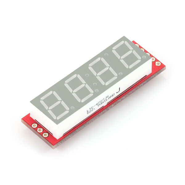
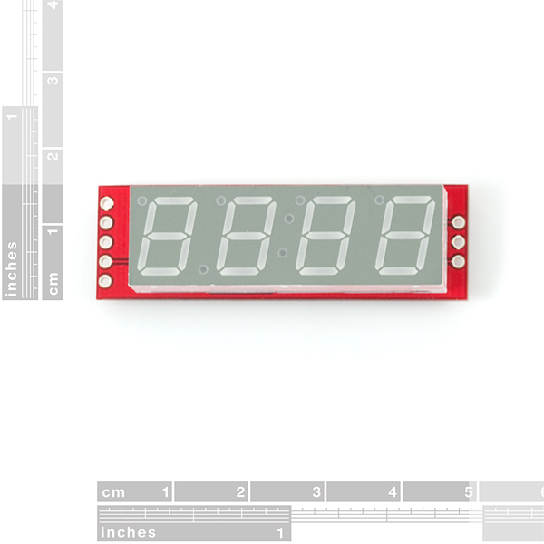
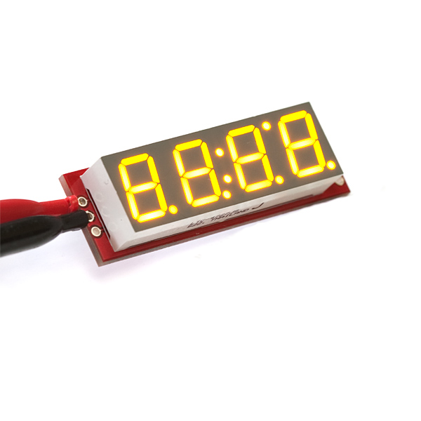
- 7-Segment Serial Display

7-Segment Serial Display
Replacement:COM-09764. We have an updated version of this board. This page is for reference only.
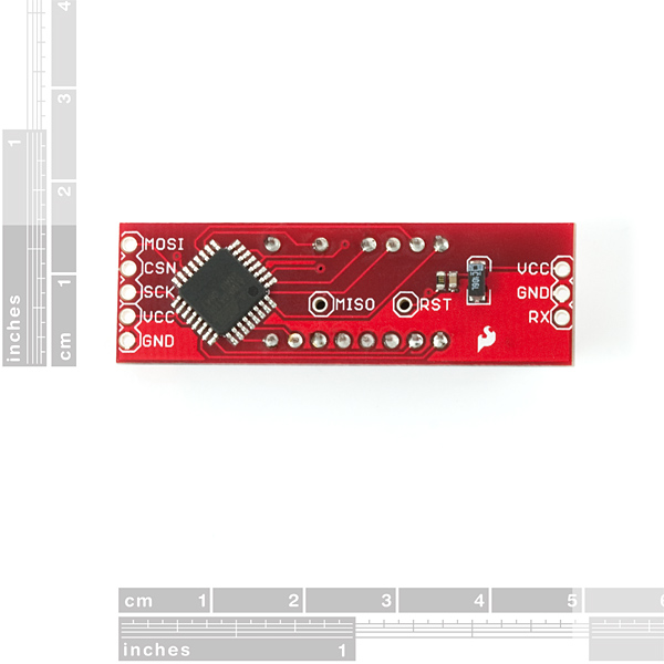
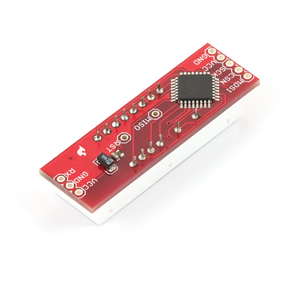
The 7-Segment Serial Display turns the thirteen pins necessary to control a 4-digit 7-segment display into just one or three. The display will give you full control of all digits, decimal points, the colon and the apostrophe. At the heart of the display is an ATMega168 which controls all the serial communications and the 4-digit 7-segment display through an easy to use API.
The Serial 7-Segment Display can be controlled in one of two ways: (1) serial TTL communication or (2) SPI serial communication. Regardless of which method you use to communicate with the display, the display is controlled with 4-byte packets and special 2-byte commands.
- 4 digit Yellow alpha-numeric display with serial (1 pin) or SPI interface (3 pins)
- Display numbers (0-9) and letters (A-F)
- Control multiple decimal points, apostrophe, and colon
- Selectable baud rate (4800 to 57600 bps)
- Selectable brightness (255 different levels)
- User's Manual
- Schematic
- Source Code (ATmega168)
Comments
Looking for answers to technical questions?
We welcome your comments and suggestions below. However, if you are looking for solutions to technical questions please see our Technical Assistance page.
Customer Reviews
No reviews yet.
Too expensive. I think is better control it with one or two "Shift Register 8-Bit - 74HC595". Not serial port needed. Control with one wire.
The reason this particular display requires a uC is that it is a matrix of LEDs. You cannot simply hold a pin high to keep a particular segment lit. Take a look at the data sheet for the bare display: http://www.sparkfun.com/datasheets/Components/C4727JS.pdf
NxN LED matrices work the same way: http://www.sparkfun.com/commerce/product_info.php?products_id=682
You most definitely can use a shift register to control this. I've done it several times and it requires much less overhead (and expense) than using an additional microcontroller to do something as trivial as this. A simple timer overflow ISR can multiplex and update the shift registers with no main program loop intervention.
Another finesse would be to move the I/O pads to the upper or lower edge of the PC board to enable the ends to be flush with the display. Then you could stack them to get 8 or more digits for counters, VOM's etc. Except for a clock I'm not sure for which app 4 digits would be enough.
Dah. Why didn't we think of that! Great feedback. We'll get them side-by-side stackable on a future rev.
FWIW, I am happy the I/O is on the ends. I'm thinking of using these in a visible glide angle indicator for wingsuit BASE jumping. The display will be helmet mounted, with an arm coming off the side. Four digits are plenty for me, since I'm looking at numbers like "2.90".
Don't change a thing! Price is great (compare to $34.95 for the SLED at Rentron), compact, no silly effects, and the SPI option is a godsend. I plan to add this to my DIY Laser Tag systems as an "ammo counter" (like the Pulse Rifle in the Aliens movie, or HALO). Flashier than the LCD display. I suspect I will be buying lots of these. If you offer more colors I will probably buy those too.
It would also be nice if this board were offered without the 7-seg display, so that you can use other 7-seg displays like the 6.5" ones.
This is a very handy little display - pretty much no reason to every buy bare 7seg displays again.
One suggestion for a future improvement:
Support additional ASCII characters; particularly '-' so that negative numbers can be displayed.
For more flexibility, add special commands for "raw" segment data. This could be implemented as four new commands, one for each digit. Their data byte would contain the 7 bits of data to directly control the 7 segments. (you could use the 8th bit as an alternative way to control the DPs).
Thanks for the steady stream of great little boards!
- Dean
Quite right Dean, this is a pretty good lil board...once you crack the nut!
Link to the sample code and wiring. Thanks again for your help.
Would be nice if we could get the breakout board (with only SMD soldered) for this for us who already have a 7-segment display.
Is it just me or does the character brightness vary depending on what the character is? What I see if I send "1818" is very bright ones and dim eights.
OK, I think I see in the issue. It seems a lack of current limiting resistors causes the current per segment to change based on the total number of segments lit in one digit (more segments = dimmer digit). It also appears that the brand new version 2 seven segment displays are also lacking resistors.
So let me ask a different question. Does this seem odd to anyone else? I realize a design goal was a tiny PCB and low cost, but a seven segment display with digits of different brightness looks really bad.
Everyone has their own ideas about how this could be more usefull for their needs.
Here's mine:
(1) 16Mhz clk (SPI could now run at 4 Mbit data transfer rate, rather than the current 2 Mbit)
(2) Binary transfer only for hexadecimal display( Only 2 bytes needed to update display, rather than the current 4 bytes)
Cheers
I noticed something odd--no current-limiting resistors for the LEDs?
Checking the source, I see the LEDs are lit in 5 microsecond pulses in about a 1/30 duty cycle at max brightness. On time could be longer if servicing a comm interrupt. Seems a little dangerous.
I'd feel a little better if the display logic was pushed to an interrupt; in my projects, I've used Timer0 for this purpose, with two ISRs: overflow cycles digits and turns the display on; compare-match A turns the display off again; OCRA controls the effective brightness. Seems you'd be less likely to accidentally leave an LED on too long this way and melt your display or MCU. It also, of course, frees up your main loop to do other things.
My first thought: an ATMega168 is serious overkill for this application. I made a camera control box (intervalometer) with an ATMega48 that drives a similar LED display. The display logic consumes something like 300 bytes of flash. The entire project consumes about 2500 bytes. 16KB for a display controller seems rather excessive.
My second thought: if that ATMega168 is programmable, I could have saved a fair bit of effort and made a more compact device too! Okay, this looks like a pretty neat device after all. Maybe if the xtal and a few other pins were brought out--and the LEDs were red--I'd build my next one on one of these instead.
The display takes 80 milliseconds to boot for all you want to know :) Measured it.
If the order of the Rx-, Vcc- and GND-pin were changed, this could mate directly with a XBee regulated explorer, making a very neat mote-display.
A quick question and a few random observations:
Q) What are the dimensions for the pads? I'd like to use this as a plugin module onto a larger board, but without the eagle files, I can't tell where to locate the pads.
1) You should incorporate some way to mount this thing. No room for mounting holes, but perhaps add two holes+pads for the SMT nuts you sell (PRT-08989). No need to include the actual nuts, though - the buyer can add them later if they want to.
2) The schematic shows the xtal pins unconnected - it would be handy if you included the pads for adding a crystal oscillator. This would make it easy to reprogram these guys as reasonably high-accuracy timers. Not really possible with the on-chip RC clock.
3) I agree with the other poster that asked for pads for all the unused pins
4) Add optional pads for an analog pin (ADC6 or 7) to be extended out to the edge through a voltage divider. This would allow these displays to be wired as voltmeters You can already do this if you repurpose the I?C pins, but it would be nice to have both at the same time.
5) You should redo the firmware so this is Arduino-compatible out of the box (it is so close already).
None of these ideas would increase the unit cost, but each would enable new potential uses for the display. Thats if for now; thanks for listening!
Cheers,
- Dean
Hey... A new firmware sounds like a great addition. St3fan, do you have a way to get the firmware onto the board?
Is there anyway I can special order this in a color besides yellow? I was looking for red, blue, and green.
Great idea! I was planning to order the SLED along with another color then desolder/resolder in the new color display.
very disappointed with this board because there's no "carriage return" or "reset" command
for some reason using NewSoftSerial, instead of getting "1234", I get "2341" etc
i'd love to upload St3fan's new firmware if I could figure out how!
First version of my modified firmware is available at http://github.com/st3fan/electronics/tree/master/sparkfun-seven-segment-display/
It supports the minus sign and has a '!' command to reset the display to a known state.
Hi Stan - you read my mind - the "-" sign and reset.
How do I get your firmware onto my board? Could you give brief description for those not so tech-savvy?
Steve
Couple of comments:
* The default baud rate for the units that I received was 2400 and not 9600 as the documentation suggested. Took me some time to figure this out
* I did not get the SPI mode to work. Sample code would be helpful. I'm using the same SPI code to talk to other SPI devices without any problem. Not sure what the problem is.
* Allow the minus sign - I wanted to use this as the display for a thermometer. It is -11C here now. But I can't display that.
* Implemented a 'reset display' command. When the display gets confused there is no way to reset it.
* Add a simple way to get to the programming pins of the chip. I will create new firmware that fixes the shortcomings mentioned earlier. I'll probably solder on wires but this is far from ideal.
When I power this display with 5 volts the digits flash very quickly making it dimmed and it will not receive any data. It work before but now it wont can anybody help?
When you power up this unit, if the RX pin is not or is poorly connected, it may pick up some random noise and the unit can do random things, eg set brightness to minimum...
...or even change the baud rate! When you have the RX connected again, try different baud rates, lowest (2400) first. When it responds, you can set the baud rate correct again.
Very handy display with some options to make it even better:
- 6 digits
- stackable
- screw holes
- i2c (multiple displays on one bus)
- 'raw' data
- programming pads
Question: How can I reset the 'cursor' position? If a glitch arrives the display show garbage but I don't see a way to 'reset' the display...
I got my displays a few days ago and I've done the hacking - still working on the code.
My page is http://nerdipedia.com/tiki-index.php?page=LED+display+hack
I was a fair bit of work and I think I'll be hacking a clockit instead next time.
My comments are much the same as before. Don't waste the TWI pads driving the display. TWI is just far too useful to ignore. The ADC pins are also valuable so the currently spare PB pins are best ones to use to drive DP and COL. If possible bring unused i/o (ADC) to pads - anywhere you can - they don't have to be on and edge.
If the software was based on the arduino boot loader people could hack the code without a programmer or ISP interface. This doesn't interest me personally though.
Eddie/eddiem.com
It seems to me you'd have to keep to temperature in a fairly narrow range to keep the clock frequency close enough for async coms to work.
I'd like a stand alone version.
It needs a regulator, ISP and xtal.
For my needs I'd want ascess the I2C pins which are currently being used to drive the display while other i/o line are unused.
Fitting this stuff would cost more money but just putting on extra footprints (pads) for hackers would be cheap.
It seems a little silly to drive this off another micro when the on-board mega168 is capable of doing the job.
Could you please post the source code like you did for your excellent SerLCD (http://www.sparkfun.com/commerce/product_info.php?products_id=9069)? i need the minus sign asap, thanks!
You got it. We'd love to hear about any changes you guys make to the code!
Take a look at this ICs from Maxims: 7219 and 7221
http://www.maxim-ic.com/quick_view2.cfm/qv_pk/1339
But I have plans for use shift registers and control output to LEDs by software. Then I have two things: an extension port for my Arduino (multiple outputs through the shift registers) and an LED controler by software using the extended outputs
Checked pricing and availability of said chip. eBay for around 8 bucks a few retaillers for 6 bucks. Still makes this little board worth it (at least compared to to maxim chip )
What does the RST pin do? I left the RX pin connected to my arduino while I did an upload and now the display is stuck in a permanent dim mode. Is there a way to reset it back to the default settings? The documentation doesn't mention the RST pin.
Based on the schematic it looks like RST is simply the MCU reset pin. It is internally pulled high so leaving it disconnected should be fine. Has the device responded to other types of inputs such as updating the digits?
Any good noob tutorials for this item?
what are the parameters for the "spi interface?" the datasheet is sorely lacking any info....
I too would like if you could purchase the board without the LEDs since I have tons of salvaged ones.
Another vote for "no reason to use a microcontroller on this board." A simple shift register would be easier and much cheaper with the added ability to serialize multiple boards.
Not that the time is a big deal, but you have to send 50% more bytes to control this over what it takes to simply use shift registers.
Price is a little on the high side but not a deal-breaker. Hard to believe these are not physically and electrically end-stackable. Need six digits for clocks, You should have enough I/O pins on the 168 for six digits if you're multiplexing - right? Need red not yellow (at least it looks yellow). Sell the boards and the LEDs separately or as a kit so we can choose the LED color.
Someone has a serial board/uC/LED matrix that has animations and other things, but it doesn't have the features of this and is 3 times more expensive, I prefer the concept this one provides, but I agree, FLUSH EDGES PLEASE :) One board could be for vertical stacking for multiple purpose displays (and multiple colors would be a must then for readability) and horizontal stacking for BIG counters/clocks/misc.
Good stuff all around! :)
Great feedback. We'll see what we can do. Footprints are not universal between LED mfgs, but should be compatible between colors.
It would also be nice to bring out any extra signals (from the ATmega168) to pads or vias so that the ATMega168 could be reprogrammed for additional purposes (like say a Tachometer).
Soldering directly to the pins on the ATmega168 will also work, but requires a bit more finesse.