- Home
- SparkFun SPI Shortcut

SparkFun SPI Shortcut
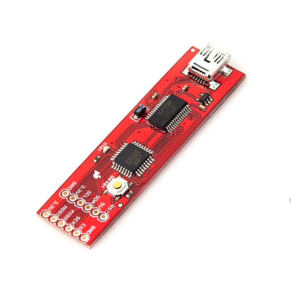
The SparkFun SPI Shortcut allows you to control SPI pins over USB, allowing for a virtual "SPI Terminal." Using basic serial commands you can access any SPI device such as sensors, media, and even program some devices. You can change all of the SPI features (frequency, data order, etc.) on the fly with no programming involved! Comes with a simple-to-use terminal interface. All you need is the FTDI USB driver and a basic terminal program.
SparkFun SPI Shortcut Product Help and Resources
Core Skill: Soldering
This skill defines how difficult the soldering is on a particular product. It might be a couple simple solder joints, or require special reflow tools.
Skill Level: Noob - Some basic soldering is required, but it is limited to a just a few pins, basic through-hole soldering, and couple (if any) polarized components. A basic soldering iron is all you should need.
See all skill levels
Core Skill: Programming
If a board needs code or communicates somehow, you're going to need to know how to program or interface with it. The programming skill is all about communication and code.
Skill Level: Competent - The toolchain for programming is a bit more complex and will examples may not be explicitly provided for you. You will be required to have a fundamental knowledge of programming and be required to provide your own code. You may need to modify existing libraries or code to work with your specific hardware. Sensor and hardware interfaces will be SPI or I2C.
See all skill levels
Core Skill: Electrical Prototyping
If it requires power, you need to know how much, what all the pins do, and how to hook it up. You may need to reference datasheets, schematics, and know the ins and outs of electronics.
Skill Level: Noob - You don't need to reference a datasheet, but you will need to know basic power requirements.
See all skill levels
Comments
Looking for answers to technical questions?
We welcome your comments and suggestions below. However, if you are looking for solutions to technical questions please see our Technical Assistance page.
Customer Reviews
No reviews yet.
WIth this produce can I directly access the SD card via a PC, If I have sd card connected to the SPI connection and the usb connected to my PC?
Again, why not just use a Bus Pirate?!?
Brilliant. The longer I work in electronics,the more time becomes a commodity and the more I try and collect tools that allow me to focus on solving unknowns. This is a 'time machine' tool.-Keith
Can this work as a SPI slave? I have a device that is SPI Master that I need to test. Thanks.
I wanted to use this to talk to a GPS receiver. The "Send ASCII characters" would have been ideal for NMEA messages, except that they need to be <CR><LF> terminated. Unfortunately the device will exit ASCII transmission mode once <CR> is detected.
If I knew how to upgrade the firmware I would love to fix that, as it is a very simple change...
Cheers,
Not very useful. The supplied firmware either sends or receives, it cannot handle receiving while sending (essential for communicating with many devices). Also, appears constrained to 8-bit data. These constraints should be listed in the product description.
Do you think this would work for Atmel/Adesto dataflash?
Can this guy be reprogrammed as an ISP for AVR micros?
From the schematic it looks like an Arduino duemilanove with less pins
Does this send I2C commands as well, the board looks like it can do I2C from the pin out names but no mention of this is the manual
Should have just bought a Bus Pirate.
From the comments above >.<
"The I2C pins are indeed a vestigial UNIMPLEMENTED feature. This device is ONLY configured for SPI communication."
Thank you, after spending the money I realized that I had wasted the $24 because they don't say anything about this in the description. I would have rather bought a bus pirate and spent the extra. This is just one of the issues I have with how Sparkfun conducts there business, I will definitely give a second thought before buying things from here again.
Yes, because the page for the redboard didn't mention "Can't slice bread" I was really disappointed when it came. Really, something called the SPI Shortcut, with no mention of I2C in the description doesn't support I2C? What a surprise.
To help users like BScode this wiki link may be of some use:
WIKI - Serial_Peripheral_Interface_Bus
I see a lot of comments about how to re-program the device and I am sure someone knows how. I would also like to change some aspects of the program to properly suit my testing application. Can someone come up with a device programming tutorial?
From what I can tell there was no boot loader included but according to the ATmega168 specification a boot loader for this device is possible. However, without a boot loader all hope is not lost because it would seem you can program the device using SPI. Is this how you do it Sparkfun? Boot loader anyone?
Here is the ATmega168 specification:
ATmega168
Okay... So I found this:
tutorials_93
Anyone want to modify it to suit our purpose?
Question.
I bought this SPI shortcut in order to talk with 3D accelerometer SCA3000.
http://www.sparkfun.com/products/8791
However when I found SCA3000 is 16bit SPI and SPI shortcut is 8 bit. I double checked the spi shortcut setting, 8 bit is not a parameter can be changed. Does this mean I could not use this to talk with my acc sensor? Any suggestion on how to fix this. thanks.
Hello, I bought a SPI module Shortcut
sku: TOL-09235.
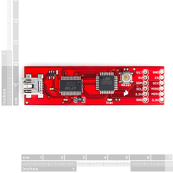
The documentation that can be downloaded from the site is that relating to the wiring diagram, on which there are 2 connectors JP1 and JP3.
Too bad the documentation I could not understand the signals.
JP3 signals are:
CS = what's the use?
SCK = Clock signal of the SPI
MISO = corresponds to the signal of the SDO SPI?
MOSI = SDI signal corresponds to the SPI?
JP1 signals are:
CS = what's the use?
SDA = SDA signal corresponds to the I2C?
SCL = SCL signal corresponds to the I2C?
Awaiting your response on Yours faithfully
Avoid this one... very limited abilities (not able to read/write at the same time).
Is there any way to re-flash the device?
This site has so many "adapters"� that simply utilize FTDI and ATMega controllers that I�d like to see them combined into some sort of FTDI-to- experimentation kit...
Actually, that�d be an Arduino. The code for these �adapters"� can be programed onto an Arduino, so long as you adjust the timing (or not).
Like Bob said, The interface is very primitive, slow, and buggy. Are there anyway to remove slow command menu, and to modify firmware and update it?
Source code added.
For those looking for I2C capability, check out the Bus Pirate
I too bought one of these thinking it could do i2c, and was hornswoggled. It don't do it.
Is there any sourcecode about that could be modified? It'd be super handy if this did i2c since when programming long device chains, you could use your SPI shortcut to pre-set device address from factory default and all.
Is there a way to get the firmware for this and reload it?
This is a great idea, but I2C is definitely needed IMHO. I'm using a DS1085Z programmable oscillator, and I2C is used to set frequency. It has non-volatile settings, so all I really want to do is "set it and forget it" for my project. This would be really useful.
Instead, I'm using an Arduino to program the 1085, because it's relatively easy, and there are a lot of examples on the web. However it would be great to have a tool that "just works" for situations like this.
I can verify the problem n4qa is having, I'm having it, too - the SPI shortcut board resets it's clock phase and speed to the default settings after a certain number of commands are issued.
This plus the awkward and slow command-menu interface make this a very poor product.
Further experiments that I have personally conducted with the SPI Shortcut have revealed the following:
Like clockwork, every eighth issuance of selection 1 under the 'ACTIONS MENU:', that is,
(1) Send command string
followed by a legitimate command string,
results in automatic hardware reset of the SPI Shortcut.
This causes the SPI Shortcut to reset to default settings for:
(1) clock polarity and phase, mode 1
(2) frequency, 500 KHz
(3) data order, MSB first
500 KHz and MSB first are ok, but, my application (AD9835 DDS control), requires clock polarity and phase, mode 3.
There are other issues with the SPI Shortcut, but they must remain broken until this arbitrary reset problem is resolved.
The SPI Shortcut holds great potential for inexpensive SPI-equipped modules to PC USB communications capability, but this potential will never be realized until this phantom reset issue is cured.
Please fix it, SparkFun!
Bill
I'm experiencing unexpected (and unwanted) resets of the 'SPI Shortcut', particularly while issuing commands from within the 'Actions Menu:'.
In researching the problem, I found this:
"Note: Currently these boards may have a hardware bug (easily fixable). The reset pin of the FT232RL is tied to VBUS which confuses the FTDI chip, and might cause a malfunction. Our next batch of these will correct this issue by leaving the reset pin floating. For now, cutting the reset pin of the FTDI chip will resolve the problem; some boards will come with this fix already applied."
My note:
My 'SPI Shortcut' has the FT245RL chip instead of the above-mentioned FT232RL chip.
Any comments on this?
Thanks,
Bill
How about a RS232 to SPI version? I have a project I'm working on where I'd like to use one com port, using RS232 Rx to recieve simple serial and need RS232 to SPI Tx, any thoughts?
whats the purpose of the status light and or the meaning of the status light?
Can the SPI shortcut be used to passively monitor an SPI bus? It would have to be configured as an SPI slave accepting an external clock - doesn't look like an option to me, but I figured I'd ask...
I should also note - it might not be a problem with this board - that the FTDI driver under Linux will lock up on my netbook. It seems to be something to do with an overrun (If I go with extremely high datarates and send data out at that rate). I get io errors, and the usb_serial module becomes busy so I can't even enumerate another without rebooting, but I don't see any kernel panics.
One of my side things is to try to create a case which shows it consistently. Right now I can get a lockup under some circumstances but it isn't that consistent.
Hi tz, I'm trying to communicate with a PWM generator (http://www.linear.com/product/LT8500) using SPI shortcut in RTAI Linux (Ubuntu). However, installation of the driver (linux 32 bit) provided by Sparkfun results in errors on RTAI linux (https://forum.sparkfun.com/viewtopic.php?f=14&t=34506). Though I'm able to connect to the device and explore the SPI Shortcut main menu as described in the user manual using kermit (http://en.wikipedia.org/wiki/Kermit_(protocol)). Could you please share the details of the C libraries you used to communicate with the device?
I already have some base I2C/TWI which talks to the accelerometer (and if PB0/IC1 wasn't occupied I have pulse-width recording). I have a few I2C devices, but it would also help to have "one of each" to see if I can talk to them, it would be nice to have a library of basic "talk to the chip/board" scripts for this connected to each of your products.
It doesn't look like there is a exactly programming interface, but that tends to use the SPI pins and rst which are there so it might "just work" with the proper fixture (or pomona chip clip).
But having the existing source would help. I need to figure out what I'm doing wrong on the miniSD breakout anyway.
Oh no, should have read these comments first. Bought this thinking that it can do both SPI and I2C only to find that it only does SPI. :(
Anyone knows where's the firmware sourcecode?
The user interface seems very primitive, slow, and buggy.
Are there plans to improve this? The unit can serve as a short term SPI checker, but is way to clunky to use for serious testing.
Is the source code available? What is the procedure to update the firmware.
I have some suggestions for improvements, some simple, some complex.
Regards,
Bob Bailey
Bailey Engineering
Wow! You guys are on point, I'd expect nothing less from our customers! pburgess, you're absolutely correct. The I2C pins are indeed a vestigial unimplemented feature. This device is only configured for SPI communication. We wanted to get this board out quickly and haven't had time yet to implement I2C, so the "Optional TWI breakout" is just that, a breakout; not yet implemented in the firmware (although if someone wanted to write that code and send it to us we would host it, not to mention squeal with delight). Sorry for the confusion. Also, somewhere down the line the acronym "UI" was made "API," and it slipped by me. That will be changed in the datasheet. Right now the device works through a terminal user interface, not an API in the programming sense. The point of this device is that no programming is required to communicate with an SPI device.
ebarajas: this device might do that already. What's a bit baffling is that I2C is implied by the first row of pins there (SDA/SCL), but a bullet point in the manual ("Optional TWI breakout") is the only minor mention anywhere. Maybe the same data gets fed to both buses, or maybe I2C ended up a vestigial unimplemented feature, not sure.
Personally I'm curious to know about the API mentioned in the product description; the manual only covers terminal-based menu use.
Beautifully-made board, as always. Two big gaps in the documentation. C'mon, SparkFun...you're better than this.
Is there a similar circuit but USB to I2C/SMBUs?
They have this: https://www.sparkfun.com/products/9903