- Home
- Product Categories
- Kits
- SparkFun Metro-Gnome

SparkFun Metro-Gnome
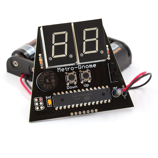
The SparkFun Metro-Gnome is a basic digital metronome used to keep time during music practice. This is a basic kit that goes together in 15-20 minutes for people learning to solder, and 5-10 minutes for those with a bit of experience.
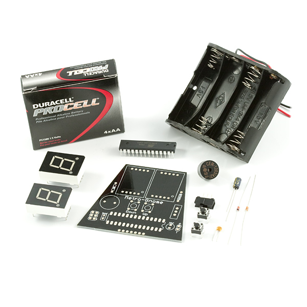
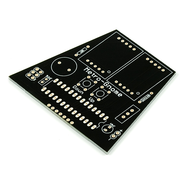
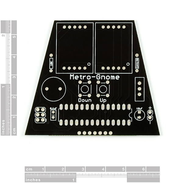
- 1 x Metro-Gnome PCB
- 1 x ATmega168
- 2 x 7-segment red LED
- 1 x 10uF cap
- 1 x 0.1uF cap
- 1 x 10k resistor
- 1 x 1N4148 diode
- 1 x Piezo Speaker
- 1 x mini power switch
- 2 x push button reset switches
- 1 x battery holder pack
- 4 x 1500mAh AA Alkaline Battery
SparkFun Metro-Gnome Product Help and Resources
Core Skill: Soldering
This skill defines how difficult the soldering is on a particular product. It might be a couple simple solder joints, or require special reflow tools.
Skill Level: Rookie - The number of pins increases, and you will have to determine polarity of components and some of the components might be a bit trickier or close together. You might need solder wick or flux.
See all skill levels
Core Skill: Electrical Prototyping
If it requires power, you need to know how much, what all the pins do, and how to hook it up. You may need to reference datasheets, schematics, and know the ins and outs of electronics.
Skill Level: Rookie - You may be required to know a bit more about the component, such as orientation, or how to hook it up, in addition to power requirements. You will need to understand polarized components.
See all skill levels
Comments
Looking for answers to technical questions?
We welcome your comments and suggestions below. However, if you are looking for solutions to technical questions please see our Technical Assistance page.
Customer Reviews
No reviews yet.
Why is there no socket for the Atmega328P? couldn't you damage the ic from soldering?
-------------------- Tech Support Tips/Troubleshooting/Common Issues --------------------
To reprogram the Atmega328P on the SparkFun Metro-Gnome, you would need an AVR Programmer to connect. There is no Arduino bootloader on the board so you would need the makefile to compile a .hex file from the code, flash the .hex file, and set the lock bits. This old tutorial might be of some use => [ https://www.sparkfun.com/tutorials/93 ].
Note: The older versions of this kit used the Atmega168. The current builds are using the Atmega328P.
Just built this up with my 10-year-old son. First electronics project ever for both of us, unless you count Snap Circuits. Went together in an evening (~90 minutes) including reading some soldering tutorials. He did 80% of the soldering. We had a couple bad bars on one of the displays, but we managed to track them to bad soldering joints on two pins, and fixed them. He's thrilled! Thanks for a simple, but useful, starter project!
My son was using the metronome while playing his guitar and suggested it would be nice to have a flashing LED along with the clicking buzzer. Simple. I soldered an LED between the AN (#3 pin) and GND (#7 pin) holes on the JP-1 connector at the base of the board. Then added a set bit and clear bit instruction for PORTC, bit 2, surrounding the while loop inside the Interrupt Timer 1 routine. Ta da.
This was my 3rd or 4th soldering project.
When together well and it was a great learning tool.
Here is a video of me putting it together:
http://www.youtube.com/watch?v=K3XfkIolhas
This was my first foray into soldering and it went incredibly well. Everything was easy to assemble and the metronome worked without any troubleshooting.
FYI, Metrognome is a song by the English progressive group, Camel.
What's with the header at the bottom? According to the schematic, it only has "AN" (PORTC2), GND and VCC. What are those? I know that somebody used it for and LED, but was that its intended usage?
Thanks,
baum
I just looked @ the schematic, and it looks like only 8 pins(PD0 thru PD7) are used to control two 7-segs... Am I reading the schematic wrong?
Actually it's 10 pins, PD0 - PD7 plus PC0 - PC1. Put the bit pattern on PD, then allow current to flow through the 7-seg of choice by outputting a low on PC0-1. Output the pattern on PD and ground one of PC0/1 to light up that 7-seg. If you switch back and forth between the two 7-seg fast enough your eye perceives a continuous pattern displayed on each.
I built the digital metronome for my wife who is a pianist. She loves it and uses it all the time. Her old metronome is now a dust collector.