- Home
- Product Categories
- Kits
- LED Cube 3x3x3

LED Cube 3x3x3
**Replacement: **KIT-09867. The new version has an Arduino serial bootloader programmed onto the ATmega328.
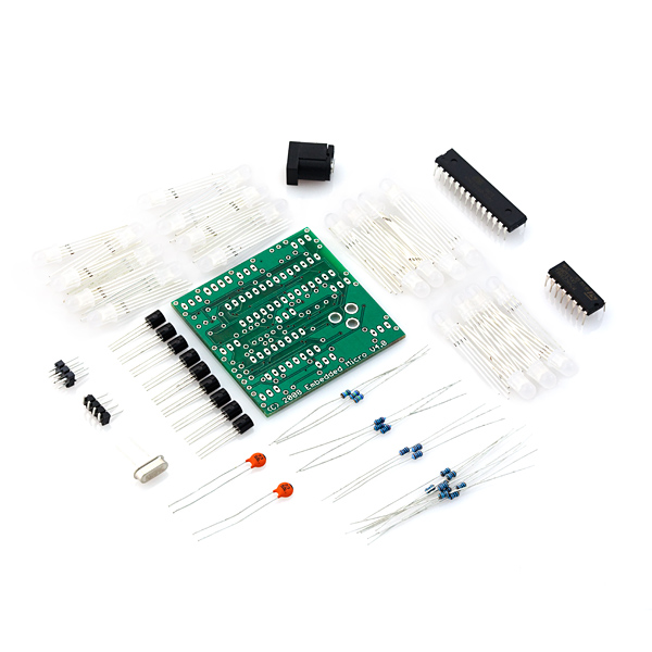
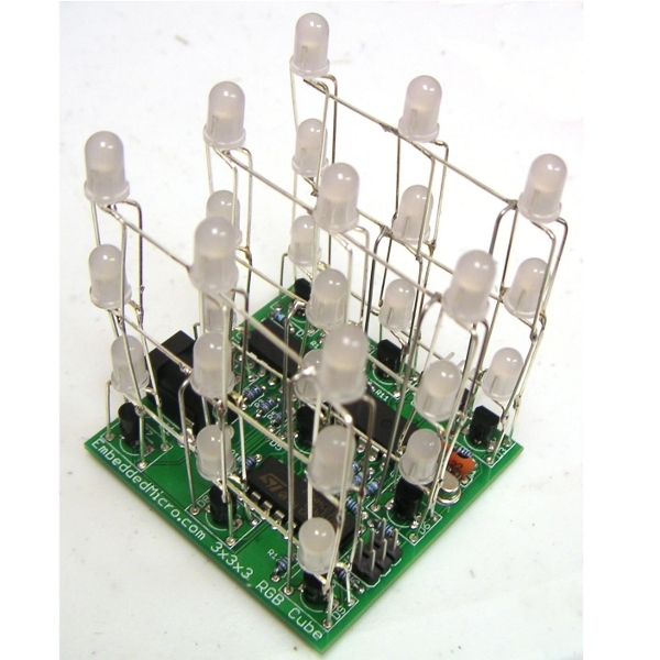
This is a kit for a 3x3x3 cube of RGB LEDs. This kit contains everything you'll need - 27 LEDs, an ATmega168 microcontroller, custom PCB and other supporting components.
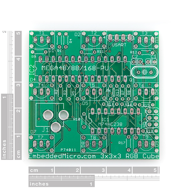
The included PCB breaks out the ISP header and the USART pins of the ATmega168; so you can customize the code and control it with a serial device. Sample code comes pre-programmed on the ATmega168.
Power should be provided by a clean +5VDC source. A 2.1mm barrel jack connector is included, but the power supply is not.
You'll need a soldering iron to put this together. All components are through-hole, but the LED matrix is a little difficult to assemble. Make sure you thoroughly read through the build instructions!
- 1x Atmega168 (pre-programmed)
- 1x 4 0.1” header (optional)
- 1x M74HC238
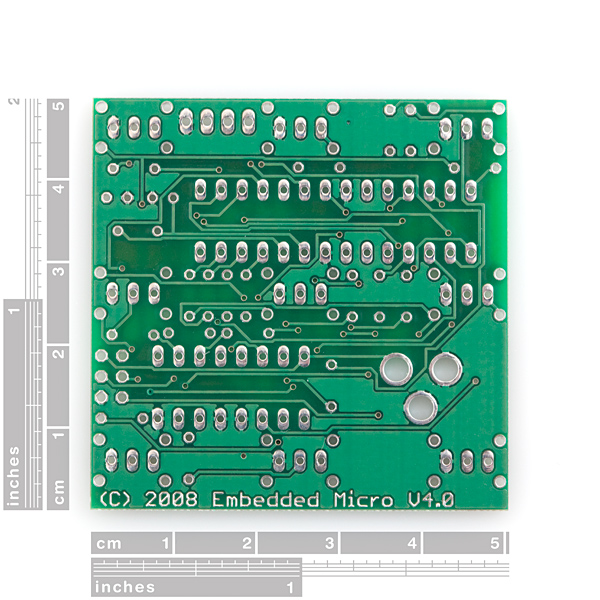
- 1x 3x3x3 cube PCB V04
- 27x RGB LED (common cathode)
- 2x 12” straight wires
- 2x 22pf capacitors
- 9x 1K ohm resistors
- 1x 20MHz crystal
- 3x 169 ohm resistors
- 1x 2.1mm DC jack
- 3x 200 ohm resistors
- 9x NPN transistors
- 3x 100 ohm resistors
- 2x3 0.1” header (optional)
- Build Instructions
- Schematic
- Source Code(YouTube)
LED Cube 3x3x3 Product Help and Resources
Comments
Looking for answers to technical questions?
We welcome your comments and suggestions below. However, if you are looking for solutions to technical questions please see our Technical Assistance page.
Customer Reviews
No reviews yet.
I don't want to arrange the LEDs in a cube, I want to arrange them in a 2D grid. I would wire them based on the schematic, but I looked at the schematic but it only has 9 LED shown on it - how do I wire the rest?
I don't actually have one of these but from the schematic and the instructions, I'm guessing its all multiplexed.
the header for D1 actually has 3 LEDs "stacked" together
[D1]
R G B <- top LED
| | |
R G B <- middle LED
| | |
R G B <- Bottom LED
The rows are selected using the C (common) pin
[D1] [D2] [D3]
RGBC-CRGBC-CRGB (row 1)
| | |
RGBC-CRGBC-CRGB (row 2)
| | |
RGBC-CRGBC-CRGB (row 3)
So to light up the top left red (D1, row 1), you would need to select D1's red and row 1 common
I'm not so sure that blue-line-multiple-outputs thing on most of the schematics is actual industry practice either.... it makes it very hard to follow. Maybe something like this : http://commons.wikimedia.org/wiki/File:MFrey_Task_1_Solution_NAND.svg
The lines coming off the micro are vertical and the stuff connecting to it uses horizontal lines.
"I'm not so sure that blue-line-multiple-outputs thing on most of the schematics is actual industry practice either.... it makes it very hard to follow."
It's called a bus. Yep pretty standard.
$69.95 = Ouch! 27 RGB LEDs elsewhere at $1 a piece in quantity is $27. That leaves $42.95 for the rest of the kit. I don't think so. I might go for $49.95.
I am having trouble reprogramming this not sure where to start and the hardware I need can someone help I really want to try an change the program around I need a cheap way to
Where can I get the source code for the ATMEGA?
I've already got all the components put together, but I can't seem to find it anywhere.. :(
Thanks
Also, the ATMega is preprogrammed, so you shouldn't need to load any code.
Ooops, nevermind... I somehow skipped over it.. I'm sooo ashamed.. :X
About the atmega, I fried mine.. :$
On this page, right above comments is a link for the source code :-)
Got one of these in my Xmas stocking and built it over the holidays. Works great but I can't reprogram it. I've tried 2 different ISP programmers (including the Pololu one sold here). Some have suggested the ATmega's fuses could be set so as to disallow reprogramming?
Has anyone else tried to reprogram one of these via the ISP jumper provided on the PCB? What did it take to get it to work?
AVR Studio with either of my ISP programmers keeps saying "Entering programming mode.. FAILED!" - bugger!
The cube can be programed and I have tested it with the AVRISP mkII, any compatible programmer should work.
Ouch, and that's one badly (auto)routed board too!