- Home
- Product Categories
- Development Tools
- WIZnet Embedded Web Server Module - WIZ200WEB

WIZnet Embedded Web Server Module - WIZ200WEB
Replacement: None. It's time for this product to step aside and make room for more cool stuff. This page is for reference only.
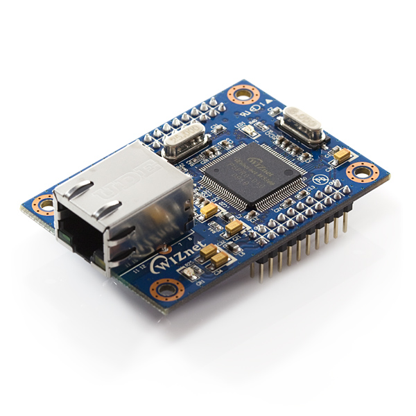
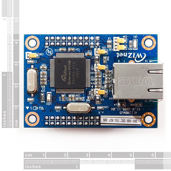
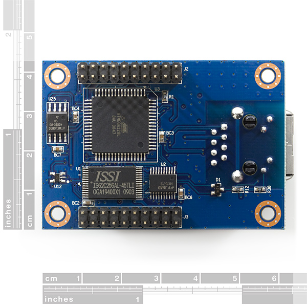
WIZnet's WIZ200WEB combines their W5300 embedded TCP/IP controller with Atmel's popular ATmega128 8-bit MCU. The pairing of those two chips turns the WIZ200WEB into a tiny, embedded web server. The webpage can be stored in the serial flash memory of the board, and can be updated through the network.
Two pairs of 10-pin, 0.1" pitch headers break out a number of handy pins on the ATmega and W5300. Power is unregulated on-board and should be supplied from a clean 3.3VDC source.
- Embedded Web Server module integrating an Atmega128 & W5300
- Operates as an HTTP server
- Available Testing
- Digital output - LED & LCD Control LCD not included)
- Digital input & analog input through web browser
- Guarantee system stability and reliability by using W5300
- Provide Configuration Tool Program
- Easy configuration and control
- Supports 10/100 Mbps Ethernet* Board: 42x60mm
Comments
Looking for answers to technical questions?
We welcome your comments and suggestions below. However, if you are looking for solutions to technical questions please see our Technical Assistance page.
Customer Reviews
No reviews yet.
For someone working with Arduine the WIZnet product might be percieved as a bit friendlier. All the ENC28J60 experimenter boards are designed around PIC boards and products.
The ENC28J60 has 1 socket and the 5300 has 8 sockets available.
Wonder if the Arduino bootloader could be put on the 128 and simplify the programming hardware that way? Also make it a little easier for an Arduino user to work with.
We have a older GPS clock at the TV Station and something like this make a nice small device to hang on the serial port and transmit the time to the computers on the network. Or setup as an NTP time server...
By the way, the communication between "WIZ200WEB Configuration Tool" and the WIZ200WEB Module is through serial (TXD0, RXD0)
Before I start I thought its gonna be through the Ethernet
Make sure its 3.3v serial, u can use the SFE "Logic Level Converter"
Just a question - Why use as WIZnet SMD chip when there is the ENC28J60? That one is DIP and has only 28 pins. Much easier to deal with. Is there an advantage over one chip or the other?
anyone know how to get it to enable DHCP by default? having to enable it every time I turn it on is a pain. I can't seem to find the option anywhere in the code.
Is there a simple break out board available for this module? I don't want to have to buy the development board.
Thanks
i am unable to locate the wiznet.rom file described in the manual to upload to the WIZ200WEB
Where can i get the file/source?
Any reason I should get this instead of the standard Ethernet shield? Or vice versa?
I was able to get mine to work OK, but I built up a homebrew version of the development board that Wiznet has for this module. I can get the LEDs to turn on/off, read the switches and pots, and display messages on the LCD display. I bought the little temp sensor chip from digikey, and that works as well. I did need to change the IP address, and enable DHCP, through the Wiznet configuration program, if I remember correctly. The enet leds work fine too.
Wiznet has a document for their development/EVM board, which shows how to use the module with the existing code on the module, go to their website. Then, try to change that after confirming the existing stuff works fine.
I plugged by Wiznet enet cable right into a standard switch port on my LAN, it gets an IP address from the router just fine, after I config'ed it to do that.
I have not tried to modify the existing code yet. But, I believe all the code is available, either here at Sparkfun, or on the Wiznet website.
I'm happy so far...
Terry, WB4JFI
In was able to get this to connect with my desktop, but no luck past that point. Looking at the Wiznet website tutorial, it looks as if their full kit comes with some additional software that would be very helpful; but the ROM-maker files shown on the tutorial are not available for download as far as I can see.
Also you have to program the MCU with an Atmel ISP programmer and I was unsuccessful doing this with my cobbled up arrangement using the ISP port of my STK500. If fuses are set on the '128 there is no way to ISP program it-- it must be high-voltage programmed. The tutorial mentions "unmounting" the '128 for this. This is not feasible with the tools available to me.
Any ideas?
Did you connect it to your desktop with a crossover cable or with a hub? Can you describe how you powered it. I have not been able to get mine to do anything. Thanks.
I have not been able to get this to operate. I hooked up the pins labeled 3.3V and GND to a regulated 3.3V source and the power light comes on, but I have not been able to see the device with the configuration tool. Also the link lights don't come on. I have tried connecting using a hub. Should I use a crossover cable directly to the device? Any help to get me started would be grealty appreciated.