- Home
- Product Categories
- Kits
- Digital Oscilloscope DIY Kit

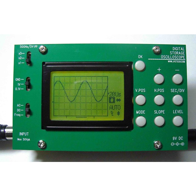
Digital Oscilloscope DIY Kit
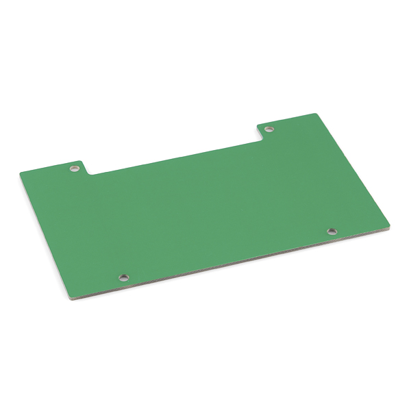
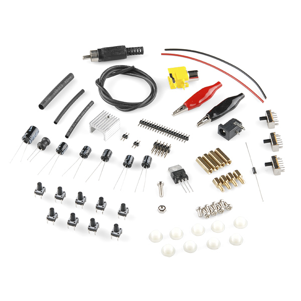
This kit includes everything you need to build your very own, fully functional, digital oscilloscope. Once you've got it up and running, the oscilloscope features up to 5M samples/second, 8-bit resolution, up to 50Vpp max input voltage, and more!
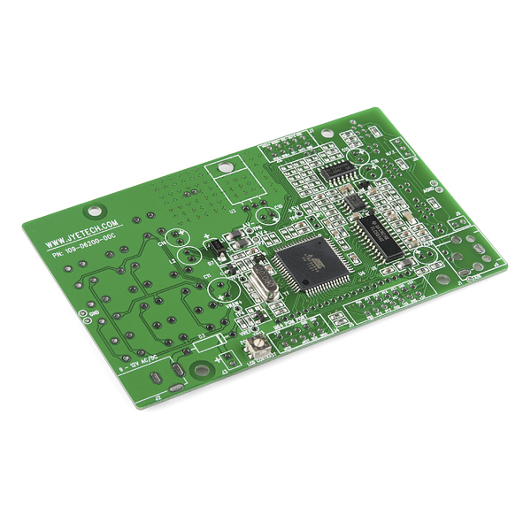
This kit includes a semi-populated PCB, with all of the surface mount components already soldered on for you. The components left for you to solder are all through-hole. This is on the higher end of difficulty as far as through-hole kits go.
This kit pairs nicely with our BNC Probe Kit! A 9V power supply is required to run the oscilloscope; supply is not included.
Note: We are now shipping a newer revision of this kit. The part number is 109-06200-00C. New pictures are forthcoming.
- 9VDC power supply voltage
- <280mA current draw
- 5M samples/second (AUTO mode only)
- 8 bit resolution
- 256 sample memory depth
- 1MHz analog bandwidth
- 100mV/Div-5V/Div sensitivity
- 1MΩ impedance
- 50Vpeak-to-peak max input voltage
- DC/AC coupling
- Save and display up to 6 captures to memory
- Transfer screen capture to PC as a bitmap file (serial adapter not included)
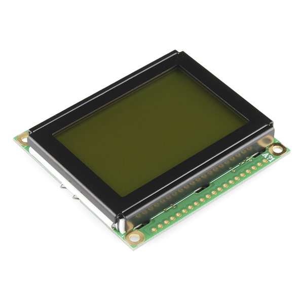
- Backlit LCD display* 110x65x25mm
- Weight: 70g
Digital Oscilloscope DIY Kit Product Help and Resources
Core Skill: Soldering
This skill defines how difficult the soldering is on a particular product. It might be a couple simple solder joints, or require special reflow tools.
Skill Level: Rookie - The number of pins increases, and you will have to determine polarity of components and some of the components might be a bit trickier or close together. You might need solder wick or flux.
See all skill levels
Core Skill: DIY
Whether it's for assembling a kit, hacking an enclosure, or creating your own parts; the DIY skill is all about knowing how to use tools and the techniques associated with them.
Skill Level: Noob - Basic assembly is required. You may need to provide your own basic tools like a screwdriver, hammer or scissors. Power tools or custom parts are not required. Instructions will be included and easy to follow. Sewing may be required, but only with included patterns.
See all skill levels
Core Skill: Electrical Prototyping
If it requires power, you need to know how much, what all the pins do, and how to hook it up. You may need to reference datasheets, schematics, and know the ins and outs of electronics.
Skill Level: Rookie - You may be required to know a bit more about the component, such as orientation, or how to hook it up, in addition to power requirements. You will need to understand polarized components.
See all skill levels
Comments
Looking for answers to technical questions?
We welcome your comments and suggestions below. However, if you are looking for solutions to technical questions please see our Technical Assistance page.
Customer Reviews
No reviews yet.
This is a fascinating piece of work. I have assembled it and written a kit review with demo video at http://wp.me/pQmjR-9n
Great! Thanks for that.
Many of these comments are old so I wanted to add some from Jan 2013. I got my kit and assembled it in 2 one hour sessions. The assembly directions are online and easy enough to follow. It's small - double check that screen size - but looks like it will be easy to find a container for it. Everything fit fine, the components were easy to fit into the spaces and it went well. I was a little concerned with some of the older comments here but it seems the problems have been smoothed out.
Like others have mentioned, some of the solder pads are small so a steady hand and a magnifying glass to inspect are needed.
The only shortcoming I saw is that there are no directions I could find for hooking the "probe" to the scope. It should be simple enough - 2 wires to solder - but it's been long enough since I have used a 'scope that I can't remember if polarity for the leads matter.
Overall, a fun little kit to build.
first thing i noticed about this when i got it is the complete lack of useful instructions. i took some time trying to dig up all the information i could on the thing.
i installed the main board parts, did the 5v test, installed jumper, tested again. everything seemed ok. i attached the headers to the lcd module, inspected them carefully to make sure they were ok.
things were going smoothly until i discovered that the heat sink was blocking one of the 2 pin headers. i had decided to simply rotate the heat sink 180 degrees.
soldering lcd headers to the main board was rather daunting, as there were several smd components very close to some of the pads. but i managed to get around them. i power up. the screen lit but was blank.
after checking some of the terminals i found several incorrect voltages, but the troubleshooting guide didn't say how to correct them. after some tinkering i got the thing to display the version number, but this only happened once or twice.
i check connections and touch up the pads but i finally came to the conclusion that i had either just bricked $60 bucks, or i had been sold a $60 brick, ether way, it sucks.
Argh... I bought one of these but the instructions and parts lists I can find are all for a DIFFERENT model board... Now my scope doesn't work and just makes an awful high-pitched whine when I turn it on!
I just grabbed one from stock and am looking at it. The instructions appear correct. Are you referring to the correct assembly notes:
http://www.jyetech.com/Products/LcdScope/Assembly%20Notes.pdf
If you have further issues, please contact tech support at techsupport at sparkfun dot com.
Since 2 people have it working, I'll accept that my completely dead one is due to something I did wrong.
I have installed what was included and added the D4 jumper, but I don't even get a backlit LCD. Some of the voltages described in the troubleshooting guide are correct and some aren't.
Tesla: Thanks for the top about jumper@D4 which led me to realize that there may be other parts than what's in the kit.
Are there any other not-included parts that are needed? Specifically - my parts did not include any hardware for jumpers, are there any that are needed?
Thanks
---Raymond
Since the D4 jumper was missed, did you catch the JP1 jumper too? Once you verify 5V at the test point, you should bridge that jumper so that it actually starts feeding power to the rest of the circuitry. That one caught me off guard for a while.
I have two of these. The first was an attempt on full diy, with all components in the bag and none soldered. It took a while and now I have no clue where the error(s) are. The next one I bought with all smd's soldered, but when I added the through hole parts, I certainly don't measure what the guide tells me I should see. What is the best forum to troubleshoot these?
Joachim
I have made it to the 5vdc test but the screen keeps dimming on me. I have checked for shorts and can't find any visually. I just found the Google Group they have which I'll try next:
http://groups.google.com/group/jye-tech-oscilloscopes
Disclaimer: I own one of these, and it is kind of a piece of crap. Granted, it's the cheapest oscilloscope you can possibly buy, anywhere, so from that point of view, this thing is awesome.
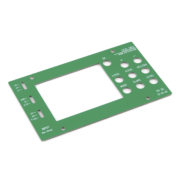
I'm not sure if they've fixed it in the newer revisions, but the front panel hole for the LCD is too small so you are going to have to route it out with a Dremel or other tool. Also, as soon as you get it, update the firmware to the latest version. The newer ones might be shipping with the latest firmware, but I know it made mine way better, it even upped the sample rate!
OK, I have it assembled and passed the 5V test. I've run into a problem.
All of the stat switches are labelled as different values, but no where in the parts list or instructions do I see which value matches to which position on the board. I'm getting the impression that they are all the same and it doesn't matter, yet each one has a different value, such as 23K, 1K, 30K, etc. stamped on the bottom. To me, that is a resistance value that matters, not some other kind of number. Especially since, to me, anyway, if they were all identical, those numbers, even if they aren't really resistance values and just look like it, would still be the same. Anyone know the story on this? Am I just missing it somewhere?
And I have another question. I'm not entirely a newbie to electronics, but neither am I an expert. This may be a stupid question, in other words :) These, as far as I can tell, perfectly square. There is no indicator that I can see or deduce that tells me what orientation these things should be in on the board. Seems to me it would matter, since these are directional in nature, i.e. you turn them left for "down" and right for "up". They each have 4 pins, but I don't see -- yet -- how that makes a difference... when one (or two) pins go low, the others go high... but if the pins are in the wrong places, you won't get expected behavior, at the least. Or so my intuition is telling me. I have a suspicion I'm missing the obvious on this one, but I admit I don't get it. Any elucidation would be appreciated.
Thanks.
cool project but poorly designed i put mine together using the build notes and i still killed it.
I recently picked one of these up. There are a couple of gray areas in the instructions, and I threw a quick assembly video together and post that should help a little bit. It makes a nice accompaniment to the instructions:
Blog post and video
Hopefully it helps!
Awesome little kit. Thank you.
semi-populated? awe man, that's no fun. =(
There are a second set of instructions for the kit written for a course at Centennial College, School of Engineering Technology, Toronto, Canada available here.
I'd like to see this kit available without the display, so user can opt for a different one of their choosing.
Aug 2013 - Quick build, beautifully compact, instructions are accurate. Running mine off a 9v battery with no problems.
I bought one of these and assembled it. It works great. It measured comparably to the professional scopes both analog and digital on the machines I work with. Instructions are a bit lacking but not impossible to follow and a little research on the internet goes a long way.(video tutorials are available for this online like Youtube). I hit a few snafus assembling it but once I did some trouble shooting (bad soldering) I got it to work perfectly. I would hardly call it a piece of junk and the guy who calls it a brick should look his handy work over making sure he/she didn't miss anything.
It measured dc voltage and ac voltage with the probe multiplier. I was able to check the house voltage and frequency. The sine wave gets cut off on the display but over all it works very well. It's a nice handy portable unit and a fun kit to build .Took me two hours trouble shooting and all. I really enjoyed it and would personally recommend it.
I am very happy with the Oscope kit. It performs as advertised and provides good troubleshooting capabilities for its price. Assembly requires some patients but if I can do it most anyone else with kit assembly experience can do it. Two previous comments that I read helped me out greatly: 1) Install the switches located next to capacitors before installing the capacitors (move 5v voltage test accordingly) and 2)Be sure to perform a trial assembly to see exactly how the LCD should be mounted to the circuit board; the header attaching the LCD could be incorrectly placed (the assembly instructions while adequate do not provide a side-view illustration showing which side of the circuit board the black header spacer and the longer length pins should be positioned on). I definitely recommend performing a trial assembly.
Mine powered up and worked fine (only minor adjustment of the display contrast pot required). A fine winter project. This SparkFun project is serious soldering, not SolderFun. Patience is required on a board designed by and for robots (which thankfully in this iteration of the kit have done all surface mount work). As other commenters indicated slide switches with pins close together, and smt and caps close by, are among the most demanding soldering points. Soldering of these switches would have been easier had the switches been inserted and soldered before the installation of the adjacent electrolytic caps. Soldering of header strips to the display, and then soldering the assembly to the pc board, required patience and repeated pleas for divine assistance.
Bought this a couple months ago, frequency meter works, scope does not. Waste of $60.
Just got one of these. It went together easily and quickly. The instructions are a little lacking meaning that you have to work some things out for yourself - but then that adds to the fun. Some of the soldering is a little tricky, so you need a nice small bit on your iron and a steady hand. As a working scope, this thing is no fluke - but it is very good and more than able to do the tasks for which it was intended. I do have a few comments, however. Firstly it is a shame the chassis could not have been made to enclose a PP3 9v battery - I have mine running off of one with no problems. Also an on/off switch on the front panel would have been very useful. Lastly, anybody buying and using this kit should be carefull what they hook it up to. The input is not overly well protected and could be easily destroyed. So don't do measuring any tube circuits or trying to fix your TV.
I bought this kit a month or so ago, and after I assembled it, the oscilloscope worked perfectly -- just as claimed. Then about a week later, I found out about the new model, the DSO 096 oscilloscope. But since I couldn't find anyone currently selling it in the US, I ordered it directly from JYE Tech in China. I had a lot of trepidation about ordering from China, but it was just fine. When a minor problem occurred with my order, JYE Tech straightened it out immediately, with absolutely no hassle. Also, I have received quick, courteous, and thoughtful answers to my questions. Based on their excellent customer service and the quality of their products, I would give JYE Tech my highest recommendation as a reliable and trustworthy company.
I bought one of these just to have a little fun and it works great for what it is. I haven't really done any soldering in the past so I had a professional solder tech give me a quick class on soldering. For the most part the assembly was straight forward and simple. The only problem I had was that the lcd backlight came on but I couldn't see anything. I adjusted the potentiometer and was able to see the screen but the contrast is not very deep. The screen is extremely faint and I have adjusted the pot to its limit. I hooked it up to an Agilent 33220A sig gen and it measures fine. I may try to come up with a fix to remedy the issue with the contrast.
Great kit. Everything went together easily in less than 1 hour. Use a decent soldering iron with a small tip as some skill is required to solder the switches cleanly. Don't put your caps in back to front and check your joints. Instructions are on the manufacturers website are clear and easy. Seems to work great for an entry level scope and no issues with mechanicals not fitting together. Very satisfied.
I purchased this kit with my Free Day money. I received the package yesterday and put it together in 2 hours. I made a couple of mistakes, spent another 30 min troubleshooting and it is working fine. The mistakes were minor. The MFT jumper should only go on pins 1 and 2, pin 3 is ground and you will get no signal. The second mistake was I installed the header pins for the LCD upside down ( long pins towards the panel is wrong ), I fixed it by putting a plastic spacer under the panel. The scope works fine, the FFT function is great.
It is a little tricky soldering the small pins for the sliders, use liquid flux. The board model was the most recent, the firmware is 2 REVs old. No major changes but I will update it this weekend using the bus pirate I also bought. Update: After figuring out how to use the bus pirate I discovered that the oscilloscope had the latest firmware. So it was shipped with the latest rev board with the latest firmware.
When I got mine, it was missing one of the SMD diodes. Too bad I didn't notice until after I fried it trying to find the problem. The company's website has the newer model, and no longer supports this model. DO NOT BUY THIS PRODUCT.
The model that Sparkfun stocked was the newer model although photos shown were not updated. Older models are still supported from the links at bottom-left corner of jyetech web site.
Just finished mine and it works great! It's the most inexpensive digital oscilloscope with storage capability that actually works that I've ever seen. Also, the switchable frequency meter capability is a nice little extra.
The instructions while containing some errors were never the less much better than most Chinese kits I've seen. I'd like to see sparkfun offer the Jyetek frequency generator DIY kit as well. I've emailed the Jyetek and they've been very responsive.
Sparkfun got the kit out to me real fast, so I'll be buying from both of them again.
Since this product got such crappy feedback, I feel I should leave mine.
I had no problem with this thing. The instructions are written in bad engrish, but you don't really need them. Just make sure that JP1 is shorted out and you should be golden.
Nice toy!
If you want, you can see a video of mine hooked up to my arduino at http://fux0redprojects.blogspot.com/2011/04/jyetech-diy-oscilloscope.html
The 06204KP just came a few days ago and this is apparently the latest version of the kit. After I got the probe completed today, I checked the dso with the internal signal and everything looks hunky-dory. When I got the lcd module installed the evening before last, I got the dreaded "backlight on but nothing else". A few random adjustments of pot1 (without concurrently viewing the screen) yielded no joy. The next morning I applied some previous experience and "exercised" the pot. Then, while viewing the lcd, I tweaked it around midrange and we had an operating dso. Yes joy!
As you may have noted, the pot only has a range of maybe a turn or less. And best results seem to be found in a fairly modest range of adjustment. If you are stuck on the "backlit and nothing else" problem, try the pot. Gently find the limits and then zip it back and forth in that range maybe a dozen or so times. Get that lube, or oxide or whatever, out of there.
I thought that jyetech did a pretty nice job on the design and execution of this little baby. The board is nice and everything fit well. That same level of skill is not present in the instructions. They should really spend a few yuan and get native speakers to help them with the docs.
Take your time with the soldering. Enjoy the process and good luck.
Paid for this partly by using my Free Day money Thank You Spark fun!!
Was easy to assembly and Solder (total noob here)took about and hour and a 1/2.
The upgrading of the firmware was tougher the kit came with the .30 version they are on 101. I have a AVR mkII programmer but could not get it to program using AVR4.
Finally figured out how to use avrdude after about 4hrs playing around.
So all and all thanks to Google(is your friend) and Spark Fun for a total learning day. :)
Did some playing around with this and should do what I need it for.
I have borrowed a more expensive scope in the past and this one gives the same answers so good enough for me any way.
Thanks
Glenn
This oscilloscope is very handy. Its small size makes it a joy to use. A useful circuit would be an electronic switch to make this a dual trace oscilloscope.
I have one of these, and it works well. But I did not know you could field-upgrade the firmware. Does anyone have a link for doing this?
I have just finished building the scope and it came with a bnc and rca connector. Did everything as quoted in the instructions and got the 5 volts on the first test. Connected the JP1 and tested again with power and got 5 volts again. I am using a 12 volt supply. Carried on with rest of the scope and plugged it in and nothing. Yes voltage everywhere but that's about it. It was a good experience to solder the lcd screen and that is about all I got from it. It's now in my box of junk and you never know I might be able to use some of the parts for something else in the future.
I finally got mine to work. the problem was rather dumb, seems the wall wart i was using couldn't provide an amp, which apparently is not enough current to power the scope. so i hooked it up to my 11.1 lipoly r/c helicopter battery, and managed to make it fully functional. cant really say how much current it wants, since all my multimeters suck. but make sure your power supply can provide a few amps. and what seems like a bricked scope might actually power up.
i kinda think my problem is with the negative voltage supply. i can get the lcd to fire up and show graphics for a couple minutes after a long period of inactivity (like a couple days). and for awhile the negative voltages are acceptable, but after awhile they go positive. at this point i dont know what do do to fix it, aside from replacing some of the surface mount components (not something im set up for or have the skill to do). at least the lcd module is still good, i might be able to use it elsewhere.
I must have been either really careful or really lucky or both because even though it took me a couple weekends to build this, it powered up, booted and worked successfully the first time.
This was my first serious SMD project and it definitely required some effort and patience. I found a couple places where I put placed something in backwards or put a capacitor in where a resistor should go, but managed to catch all of that before actually powering it on.
Oh, I have the RCA connector on my kit.
Well, If Technician4 is correct about the revisions of the board, i.e. the latest is 06204kp, then this maybe the source of many problems others are having. I wonder how many of those who had problems contacted tech support? I talked to tech support and was told that the company has placed an order from thier supplier (this is not one of thier products). Hopefully they will get the latest level boards - delivery sometime in Sept. So I am going to wait till then before placing my order, and I will make sure that I get the latest level board
The version currently in stock is 06202KP
i just purchased this unit and have subsequently found out it is among the 'older models': i was shipped 06202kp, there was originally a 06201p and 06201kp. the 'improved models' (JYEtech's phrase) are 06203p, 06203kp, 06204kp. this is kind of important because if someone is purchasing this here after having read a recent review they are unlikely to get all the functionality presented to them. the older revision boards are not firmware compatible with the newer revision boards. i'm not crying foul, i just think a good part of the frustration experienced here is due to the sparse documentation and link between it's revision and the board revision. what would be really helpful is having a clear link between board revision sold and assembly instructions listed on this product page.
I purchased the kit, and tried to follow the ambiguous directions. It was a total fail and after a few hours, I tossed it into electronics recycling.
I suggest to anyone reading this that they save their money and go for the somewhat similar assembled scope. That way you will get something you can use. For me this was a time consuming, frustrating and ultimately unsuccessful project.
And if you are wondering, I HAVE successfully put together many kits. This one has a poor design and incredibly poor directions.
Not at all up to the usual quality of SparkFun! Avoid this kit, read the other reviews!
Hi Guys,
We are very sorry for the frustration related to this kit. We are working on obtaining a new set of directions to assist with building this kit. We have successfully built one of these kits here at Sparkfun, however, it is not one of our products. We are working on this problem, and hope to come to a solution shortly. Please contact tech support if you are experiencing issues.
Thanks,
Timothy
Sorry, i forgot to add that the pic that i saw with JP1 jumped was the actual completed board on the manufacturers website (jyetech.com)
I fumbled with it for hours with incorrect voltages and a unlit LCD untill i paid attention to the rear circuit board pic where it shows JP1 jumped. when i connected it it worked perfectly.
P.S. it is a great little kit but it really needs to be better documented.
Sorry you had the problem. Did you see the instructions on this product page?
Step 5. "... short JP1 ...."
The instructions are a bit sparse though. Sorry you had an issue with that, it's easy to miss!
I built one and it seems to work. I have multiple real CROs I don't plan to use it.
I was hoping to hack it for some other purpose but the source appears to be closed and I'm not going to bother writing from scratch. I'll be putting my time into coding for the nokia knockoff or an OLED instead.
It would be nice if some of the source could be opened up. Even if complete CRO code remained closed some of the drivers (LCD) etc could useful.
Slick little kit, works well, but there are some key points that took some work and reading to figure out about it.
A: The parts list (not included in the kit) does not match the parts bag. The notes in the assembly instructions (also not included) don't line up with the board or parts bag.
B: The assembly instructions themselves are greatly lacking.
C: Useful notes if you're building this kit: Install the lone diode at position D3, and a jumper at D4. If you use the power jack, you do not have to install J3 (it's also used for applying power, but is not required). Bolting the VR and heatsink to the board may short the heatsink against a pass-through. Finally, you may want/need to trim the flange on the 3 button caps nearest the LCD, so they don't hang up against the LCD.
This is a cool little kit. Inexpensive and a slick design.
However it's probably not the most amazing diagnostic tool. I've never owned a real scope, but I was trying to use this to debug a remote reset circuit for an arduino, and found that attaching the probe to the reset pin of the arduino completely changed the behavior of the circuit. I'm pretty sure that's not supposed to happen. :-)
[disclaimer: It's possible I messed something up when building the scope kit or my circuit was exceptionally fragile or something.]
Yup, I think it's something with your circuit. I attached this to a basic hello-world LED blinking program timed to 60 Hz and got the expected square wave with no averse effects to the actual blinking LED
It is an RCA connector, even comes with an RCA plug for making your own cable to use to hook up to the scope. And the BNC kit comes with an BNC to RCA adapter so all's well with the combo.
Time for me to get soldering.
By the above note, is this the version with the bnc? All other sources for this kit I've seen come with an RCA connector. Even the images you posted show the rca.
Otherwise you will need to order a bnc connector to use the mentioned bnc probe. The board is set to allow for a board mounted bnc connector. I've built this one.
cool little scope.