- Home
- Product Categories
- Power
- ATX Connector Breakout Board

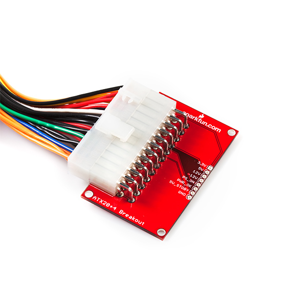
ATX Connector Breakout Board
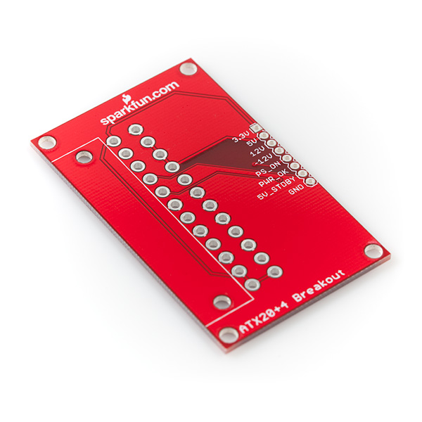
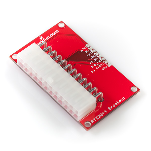
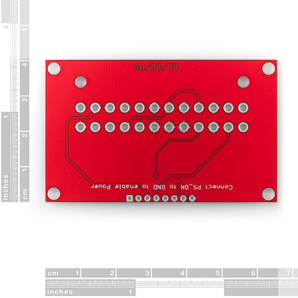
This is a breakout board for our right-angle, 24-pin ATX connector. Pair this board with the ATX connector and a standard PC power supply and you'll have 3.3V, 5V, and ±12VDC to supply to your project. Make sure you ground the PS_ON pin to enable all of the outputs.
All outputs of the power supply are broken out to an 8-pin 0.1" header.
**Note: **This product is just the board, the ATX connector is not included.
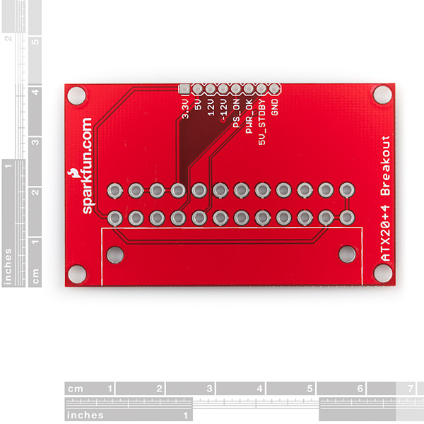
- 2.60 x 1.60" (66 x 40mm)
ATX Connector Breakout Board Product Help and Resources
Core Skill: Soldering
This skill defines how difficult the soldering is on a particular product. It might be a couple simple solder joints, or require special reflow tools.
Skill Level: Noob - Some basic soldering is required, but it is limited to a just a few pins, basic through-hole soldering, and couple (if any) polarized components. A basic soldering iron is all you should need.
See all skill levels
Comments
Looking for answers to technical questions?
We welcome your comments and suggestions below. However, if you are looking for solutions to technical questions please see our Technical Assistance page.
Customer Reviews
No reviews yet.
Would like to see more pinouts per voltage (at least two each!) and a matching number of GND lines per voltage out. Plus one for the PS_ON line. Ideally, put the PS_ON and the GND in a 2x1 header config so we could solder on a header for a jumper/switch.
I'm going to second this. More grounds are a must as this will be maxed out as a return-path in no time. A built-in switch for the power would be very nice in parallel.
Perhaps even a place for an NPN transistor to be optionally end-user soldered so a micro can rather safely turn this on.
For the next version, it would be cool if there was a switch on the board to ground PS_ON.
And a PW-OK line latch indicator LED: when power goes bad, it stops shining an LED. Also way thicker traces on the PCB (come on, you guys got plenty of space for that!)
Yeah... thicker traces plz. the PS I'm using can do 25A @ 5V and 25A @ 3V. Those don't look quite thick enough!
You should make a breakout board that uses the straight connector.
I thought there had to be a large resitor to help stabilize the power supply. Please see below from http://web2.murraystate.edu/andy.batts/ps/powersupply.htm
"
Power supplies in today's computers are known as SWITCHMODE or Switching Mode power supplies and require a load to continue to operate after being switched on (the term switching mode actually applies to the technique of A/C to D/C conversion and not to the power up action). This load is provided by a 10 watt, 10 ohm wire wound load resistor (sandbar - about $0.80 at Radio Shack) across the +5 volt supply. While many of the newer power supplies will Latch_On without a preload, you will find that adding the resistor will (1) increase the measured voltage on the 12 volt rail slightly and (2) help stabilize the voltage level in this rail by minimizing voltage drop when the powersupply is loaded with a charger.
"
Please let me know if this is incorrect or how to tell which supplies wouldn't require the resitor.
Generally this is not true. The very, very cheap power supplies that require you to waste several watts of power to stabilize their output voltage are the same power supplies that tend to go up in smoke on their own. To illustrate why it's safe to draw no (or nearly no) power, consider that there are many points in the sleep/wake cycle of a computer, as CPUs and GPUs are being powered up/down, where minimal amounts of current are being drawn on the 12V and 5V rails. By the aforementioned logic a power supply could become unstable and possibly fail during sleep and wake events, which we know is not the case.
Oh man...I am trying to design an enclosure for this and there are no dimensions on the holes...
The dimensions on this are wrong. The board is actually 66x41mm, mounting holes are 3.5mm diameter and 1mm offset from the edges.
Dumb question, but I see a -12V (negative 12 volts) line. What's with that?
It's part of the ATX Power supplyz standard. The -12V was to deal with RS232 Voltage levels as far as I know, and isn't really used much anymore. If you meant more generically "negative volts? what's that?", voltage is a potential difference, so the difference between +12V and GND is 12V, and the difference between GND and -12V is 12V, while the difference between +12V and -12V would be 24V. A negative voltage can be useful as a reference if a signal you're dealing with swings around '0V', sometimes positive, sometimes negative, so that you can use, for example, an opamp to figure out what it's doing.
You guys always seem to have what I want. I have been looking for a decent way to use an automotive DC-DC converter: http://www.mini-box.com/M3-ATX-DC-DC-ATX-Automotive-Computer-car-PC-Power-Supply?sc=8&category=101
This coupled with your right angle connector is just about perfect. I had been looking for PC/104 power supplies as this is for a PC/104 system, but I cannot find anything with enough on the 12V rail that does not cost $600 to $700! It is just crazy to pay that for a power supply. I ordered 2 of those supplies and it dwarfs the specs on the overpriced supplies. Now I just need to get your boards for easy hookup, and some Sugru for mounting and I will be set.
Design Guide for Desktop Platform Form Factors
That is a very handy specification document which all ATX power supplies are suppose to abide by. Some of the interesting things:
All ATX power supplies must have short-circuit protection and remain working after power cycling and removing the fault.
All ATX power supplies must implement de-bounce circuitry on #PS_ON.
A power supply must continue providing nominal voltage values on all lines for 15ms after being unplugged from AC power
Also, I don't see anything about needing a load across +5V to maintain proper voltage. Of course, this is the theory document... In theory, all ATX power supplies should abide to it. In practice, it's cheaper to leave out a few things
For use only with the right angle connector, the straight connector (has I have come to realize) has tabs on the side that don't have corresponding holes on the board.
At first glance. I starting pulling my hair out looking for traces for the ground as they appear non existent. rest assure my ohm reader confirmed they do exist, this must be at least a 3 layer pcb. maybe it has some more traces hidden to reveal better amperage then some people where worried about.. Thanks sparkfun this is better than nothing but some extra features would be nice like a few mentioned in the comments below
As in many, many boards, the ground signal is connected with a filled polygon - most of the copper on the top and bottom sides of the board (everywhere that's bright red except for the narrow traces) serves as one big ground connection. If in doubt, scrape away the bright red soldermask and test the copper layers with a multimeter.
I love how this is going to save me some work, but yet it after I purchased it I was thinking too late, that fuses would be good when a atx is able to spit out 20 amps and I only need a 1 amp or 2 most often. Most atx psu's have a internal fuse but, by the time that kicks in you might have some sparks, burns, or worse.. a switch would be nice too
The traces are TOO small to use for any real power applications. Provide a screw terminal block that can handle 10 to 20 amps. The main pictures show the board with the connector even though it is NOT included. I now see in normal size text that this is just the board only. Any notes should be highlighted by color and size to call attention to the note. The picture is false advertising. I won't order the connector until I can justify the shipping cost.
I Agree, pretty much only good for a few 100Ma with those trace sizes. I didn't take much notice of the pictures before ordering and was pretty disappointed with it when I got my hands on it.
this little breakout has been awesome sofar.
i have collected a small number of PSUs over the years wich i can finnaly use for my projects. so far ive had to rely either on simple weak ACDC adapters or a set of rechargeble batteries to power my experiments. now i finnaly have a reliable powersource for the more demanding projects.
The traces on the PCB look pretty small...maybe too small to carry up to 30A of current. How wide are the traces, and how wide would they need to be to source all available power from a fairly large ATX supply?
Even assuming 100% efficiency of the power supply, how do you plan on drawing 30 amps? You'll have to find an appropriately rated IEC C13 cable and an outlet fused to that level of current.
See:
http://www.sparkfun.com/products/9539
Output:
+3.3V@20A
+5V@30A
+12V@15A
-5V@0.5A
-12V@1A
+5VSB@2A
30 amps at 5 volts DC is different from 30 amps out of the 120v AC wall outlet. P=VI
Anyone know where i can find the eagle part file for the atx connector?