- Home
- Product Categories
- Development Tools
- Danger Shield

Danger Shield
Replacement:DEV-10115. The new shield uses a different temperature sensor. This page is for reference only.
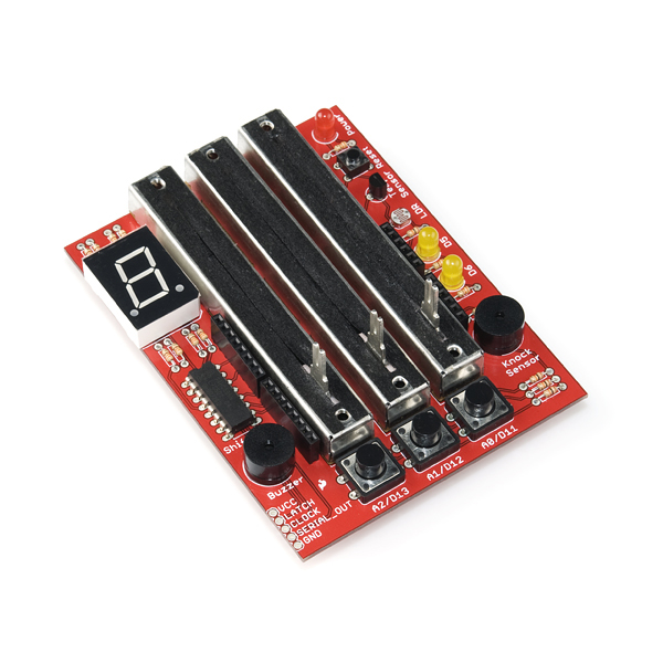
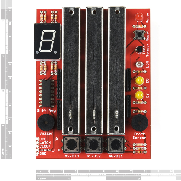
The Danger Shield mounts on top of your Arduino or Arduino Pro and equips it with a variety of fun and useful inputs and outputs. The Danger Shield has so much potential; we can't wait to see what you're able to do with it! The shield's features include:
- Three linear slide potentiometers connected to the Arduino's analog pins 0 through 2.
- Red and yellow LEDs connected to digital pins 5 and 6 - PWM pins - so you can easily vary their brightness.
- Three momentary push buttons connected up to the Arduino's digital pins 10 through 12. Those lines will go low when the buttons are pressed.
- A photocell and a temperature sensor, both with analog outputs, are connected to the analog pins 3 and 4, respectively.
- An 8-bit shift register set up to control a blue 7-segment LED.
Two buzzers - one is used, as you'd expect, as a speaker, the other is connected to analog pin 5 and can be used as a knock sensor.
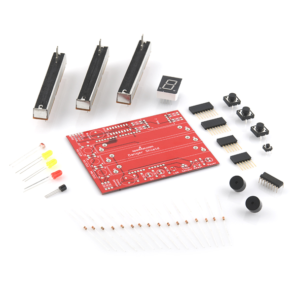
This product comes as a kit of parts, which you'll have to solder into the included PCB. All parts are through-hole so it should go together relatively easily; but always check your component orientation before soldering!
- 1x PCB Danger Shield Kit
- 3x Slide Potentiometers - 10K
- 1x 7-Segment LED - Blue
- 1x 8-bit Shift Register - 74HC595
- 1x Temperature Sensor - LM335A
- 1x Miniature Photocell
- 2x Buzzers
- 1x Basic LED - Red
- 2x Basic LEDs - Yellow
- 1x Mini Push Button
- 3x Momentary Push Buttons - 12mm Square
- 11x Resistors - 330 Ohm
- 4x Resistors - 10K Ohm
- 1x Resistor 1M Ohm 1/6W
- 2x 8-pin Arduino Stackable Headers
- 2x 6-pin Arduino Stackable Headers
Comments
Looking for answers to technical questions?
We welcome your comments and suggestions below. However, if you are looking for solutions to technical questions please see our Technical Assistance page.
Customer Reviews
No reviews yet.
Just got the kit and built it, and am trying to write some code. I ran into a problem with the temperature sensor while trying to make sense of it's output.
Then I looked at the schematic. And then the data sheet of the LM335A. I don't think it's wired properly. The datasheet (and sparkfun page) seem to suggest putting a resistor between Vcc and the LM335, and using the voltage at the point between them as output. Pin 2 seems to be for calibrating the LM335 with a pot, not for reading from. Am I missing something obvious?
I haven't delved into the schematics for my new danger shield yet, but (apart from the shift register which I have yet to solder onto the board,) the temperature sensor seems to be nonfunctional when attached per the stencil on the PCB. All other components appear to be working as expected.
You are correct that the LM335 is wired differently from spec. The reason for this wiring is that in this configuration it works as a temperature sensor and requires no additional parts. The ADC value increases and decreases when the device is heated/cooled, but it does not increase at 10mV/K as the datasheet states. I've added a resistor to the design as per the "simple measurement" application in the datasheet. It can't be calibrated, but it will deliver a more accurate measurement without increasing board price.
Noted. We are looking into this. Thanks.
Holy crap, this thing is a "transporter" control in the making! Now, to connect it to the matter stream buffers and Heisenberg compensater...
Schematic and code here is outdated! See https://www.sparkfun.com/tutorials/274 for a more recent version with a working cap sense test.
Is it just me, or does the parts list need updating? I only received 1 buzzer, and good thing, because the board I got has a spot for a Cap sense where the second buzzer is!
I think somebody misread a part number. The original design calls for an LM35, not an LM335.
http://www.national.com/ds/LM/LM35.pdf
I built this board up last night and everything seems functional except the knock sensor. Both the buzzer and the knock sensor measure out at 18 ohms (the 1meg just does not matter) and the buzzer works fine. However i am just not getting a usable value from the knock sensor analog input. Since the original knock sensor was based on a piezo element and this is a coil element, is it possible that it just is not sensitive enough?
Any suggestions on how to get it working?
thank you
tom w wolf
The knock sensor takes a pretty hard tap to get a response. Blowing on it works very well though.
Assembled one last night. Works like a charm. If you want the REAL thing, buy it from Zach (zachhoeken). The sparkfun version does not include LEDS in the slide pots.
More example code may be found here:
sourceforge.net
All in all, awesome shield.