- Home
- Product Categories
- LCDs and OLEDs
- Graphic OLED Color Display 128x128 - Carrier Board

Graphic OLED Color Display 128x128 - Carrier Board
Replacement: None. We are no longer carrying this display, but check out our other LCD and OLED displays! This page is for reference only.
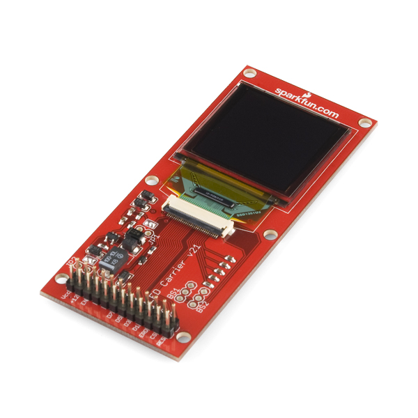
This new revision uses a new boost IC and an updated version of the screen. This is a simple carrier board for the OLED display. This board breaks out all interface pins and includes a DC-DC step up circuit allowing single supply operation.
Board comes fully assembled and tested with included OLED display.
**Features:
**
- 8 or 9-bit Parallel or 4-Wire SPI Interface
- Driver: SSD1339
- All pins broken out to a 2x12 0.1" pitch header
- OLED can be seen in daylight without backlight
- 18-Bit Color resolution : 262,140 colors!
Replaces:LCD-00763
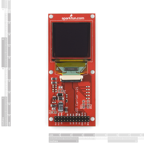
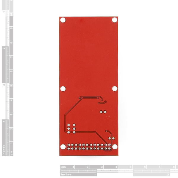
- 1.60"x3.85"
- Schematic
- Datasheet
- Example AVR Code by Cathy Saxton
Comments
Looking for answers to technical questions?
We welcome your comments and suggestions below. However, if you are looking for solutions to technical questions please see our Technical Assistance page.
Customer Reviews
No reviews yet.
This looks like a great board, but it's more than twice as big as it has to be. Put the LCD on one side, and the boost circuit on the other!
Also, I'd be highly in favor of adding pads for an SMD header, so that the through-hole parts which some people will want or need can be cut off.
Might just have to revisit this board and try out BatchPCB. It could probably be done for close to the $25 markup you're charging for the board and boost regulator...
So anyone successfully used this thing in SPI mode?
please sparkfun, provide some working avr code.
the one linked is for the older version and does not work here.
I would love to see an Arduino tutorial with code for this!
I give up :(
I got this board 10 months ago and when it arrived I tried to make it work via SPI. It didn't and I used some other oled screens that did for a while. Now I revisited this board trying again both SPI and parallel mode. After rewriting the code for pic32 and it didn't work I used exactly the same code from avr example on atmega644 (what code was written for) and this board still don't work :(. So I assume the board is faulty and not the firmware :( .... too bad I spent more then 100 hours trying to make this piece of .. work ..
So, I've been playing with this for a while and have a few thoughts:
1) Sparkfun, please stop saying its the SSD1339 - the 1339 has many more graphics functions than the 1335 which is what you are now using.
2) As reported elsewhere, when using this, you get weird horizontal lines (slight darkening of pixels on rows where some pixels are different)
Any chance you can link the 1335 manual that describes this device properly? I only found SED1335 and BS1/BS2 don't exist there .. The SED1335 (SEIKO EPSON) states that VDD is 2.7 to 5.5V !!!
Can this really work on 5V???
I believe 2.7V to 5.5V is the correct range.
That is a bold statement taking into account that both SF's doc and manual for SSD1339 state that VDD=2.4-3.5V and VDDIO=1.5V - 3.5V
The 5.5V is mentioned in Epson's SED1335 that does not mention BS1 and BS2 so it might not be the chip from this board. If you have link to SSD1335 that is "from this board" please share :)
The oled data sheet says that the absolute maximum for VDD is 2.75v, yet you guys drive it with 3.3v. Is this ok?
Anyone have sample code for this display running on the Arduino? I've tried the Example AVR Code in the Documents section but I just get a ton of errors.
AdaFruit has a 96 x 64 pixel version and Arduino demo code for the 1331 controller. Has anyone tried the code with this one?
i agree an arduino sample project would be very helpful for us beginners.
Is there a chance one can check if one has LCD-09676 or LCD-00763? All pictures of both product look same and I have no idea if I have one or another.
I can't get this one (or the LCD-00763) work SPI .. tried every trick I know ..
Check that you're using the right clock and data lines, if I recall correctly D0 and D1 are the two in question and on mine I had to swap which was clock and which was data
tried that too, no luck :(
If you managed to make it run as SPI .. do you mind sharing code and schematic? I don't really care what mcu you are using :) (I prefer C if I can chose)
They really should operate the same way. Your code doesn't really need to be different.
Sparkfun, please update the datasheets here. The breakout board manual still links to the much nicer 1339 OLED driver
Does SparkFun actually have a picture of this working? Is the controller used the same as before? (That is, will the same code work to get it running?) I will be thrilled if it's a drop-in replacement for the discontinued OLED.