- Home
- Product Categories
- Sensors
- Barometric Pressure Sensor - BMP085 Breakout

Barometric Pressure Sensor - BMP085 Breakout
Replacement:SEN-11282. We've made some minor hardware changes including the addition of a solder jumper to disable the I2C pull-ups.This page is for reference only.
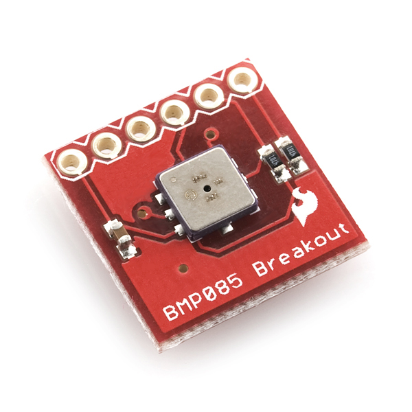
This is a simple breakout board for the BMP085 high-precision, low-power barometric pressure sensor. The BMP085 offers a measuring range of 300 to 1100 hPa with an absolute accuracy of down to 0.03 hPa. It's based on piezo-resistive technology for EMC robustness, high accuracy and linearity as well as long term stability. This sensor supports a voltage supply between 1.8 and 3.6VDC. It is designed to be connected directly to a micro-controller via the I2C bus
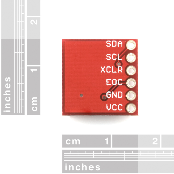
This breadboard-friendly board breaks out all pins of the BMP085 to a 6-pin 0.1" pitch header. The analog and digital supplies (VDDD and VDDA) of the BMP085 are tied together and broken out to a single pin. We've also put two 4.7k pull-up resistors on the I2C lines.
- Digital two wire (I2C) interface
- Wide barometric pressure range
- Flexible supply voltage range
- Ultra-low power consumption
- Low noise measurement
- Fully calibrated
- Temperature measurement included
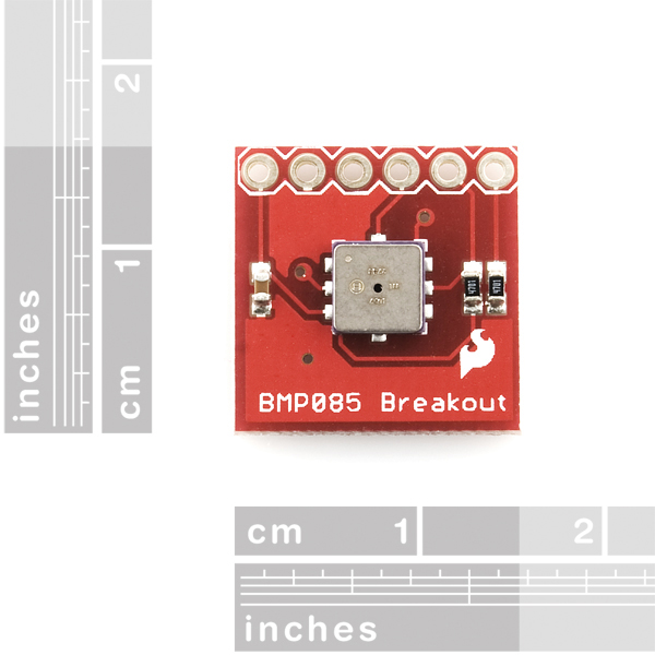
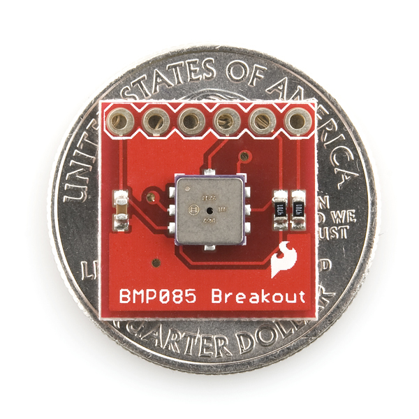
- Ultra-flat, small footprint* 0.65 x 0.65" (16.5 x 16.5 mm)
- [Schematic](http://cdn.sparkfun.com/datasheets/Sensors/Pressure/BMP085 Breakout-v11.pdf)
- [Eagle Files](http://cdn.sparkfun.com/datasheets/Sensors/Pressure/BMP085 Breakout-v11.zip)
- Datasheet (BMP085)
- Quickstart Guide
- Example Arduino Sketch
- [Example Code](http://www.sparkfun.com/datasheets/Sensors/Pressure/BMP085 Example Code.zip) (ATmega328)
- Product Flyer
- Wiring Example
- mbed User Review
- Bildr Tutorial
Comments
Looking for answers to technical questions?
We welcome your comments and suggestions below. However, if you are looking for solutions to technical questions please see our Technical Assistance page.
Customer Reviews
No reviews yet.
I did a test of this sensor relative to GPS altitude on a drive down highway 38 from Sugarloaf CA (near Big Bear) to Mentone, CA.. The results, as well as the Arduino code needed to reproduce my experiment is here:
http://sites.google.com/site/wayneholder/gps-vs-barometric-altitude
Wayne
That was COOL!
Got this working on Arduino Pro Mini, here's the full code:
http://mitat.tuu.fi/?p=78
I believe that there is a calculation error in this code which gets worse as sensor oversampling increases.
It occurs in the lines where it is setting b3:
if (oversampling_setting == 3) b3 = ((int32_t) ac1 * 4 + x3 + 2) >> 1;
if (oversampling_setting == 2) b3 = ((int32_t) ac1 * 4 + x3 + 2);
if (oversampling_setting == 1) b3 = ((int32_t) ac1 * 4 + x3 + 2) >> 1;
if (oversampling_setting == 0) b3 = ((int32_t) ac1 * 4 + x3 + 2) >> 2;
These lines should be replaced by the datasheet and API formula:
b3 = ((((int32_t)ac1 * 4 + x3) ## oversampling_setting) + 2) >> 2;
where ## is meant to be the shift-left operator (sparkfun strips 'less-than' characters out of posts)
With a raw temperature reading of 31908 and a raw pressure reading of 320701 at ultra high resolution, the first code snippet gives me a true pressure of 118662. However, when using the second code snippet (which I believe to be correct) I get 100296 - which is within 1hPa of my local weather station.
I tried the formula from the datasheet "B3 = ((AC1*4+X3)
I tried the formula from the datasheet "B3 = ((AC14+X3) [left shift] oss + 2) / 4 ", which through operator precedence(http://en.wikipedia.org/wiki/Operators_in_C_and_C%2B%2B#Operator_precedence) is "B3 = ((AC14+X3) [left shift] (oss + 2)) / 4 " , and it gave results that were very wrong. Using the formula here (http://mitat.tuu.fi/?p=78) which you have incorrectly copied in case 3, worked well for me.
I am now wondering if I use the datasheet formula with parantheses as you have would work.
I used the formula from the datasheet and got pressures that were way off.
Btw, the datasheet formula is "B3 = ((AC1*4+X3)
The < character is only stripped from code blocks, not from all comments. The full documentation is here.
PS. If you use reddit, it is the same syntax.
I used one of these sensors and 50 ft of 3/8" air compressor hose along with about $10 worth of other parts to make a secondary driveway vehicle sensor. When used with my IR sensor (already hooked up to a fio with an xbee attached), I can tell vehicle direction, i.e. ingress or egress. This sensor has a fast enough response that even a slight bump in pressure is detected at rates faster than 50ms intervals - plenty of time to detect a vehicle rolling over the hose. Really impressed with this sensor!
I'm running into some issues with my code and I hope someone could help. If I hard code the readings and calibration data that is shown on P.13 of the datasheet, I get the results shown in the datasheet, however, when I pull the real data and the real calibration off of the device, the pressure is way low (about 3.55psi, 24,500 Pa). The temperature readings are accurate, and when I change the oversampling, the results I get for pressure are consistent (about the same + expected noise) for oversampling of 0, 1, 2 and 3. I did have to play around with typecasting a bit to get things to match up with the reference code. I'd like to experiment with some other calibration data and readings to validate my calculations- at the moment, I have:
Oversampling (for this example) is 2
UT reads as 35405, which calculates to 21.5C
UP reads as 171740 (after the shift for oversampling), which results in a pressure of 24957, or 3.619psi. (way too low for my altitude, about 800ft ASL)
I'd appreciate if someone could either run my calibration an readings into their code and see if they get the same, or send me your calibration and readings I could run through my code.
FYI: this is being done in C on a PIC32 on a Digilent Uno32. I do plan to share the code once it works. I've got a bunch of things running on the same I2C bus under a scheduler I wrote- each sensor can have a different interval and it can do other operations on a different device while the I2C while the pressure sensor is waiting the requisite time.
I tried your values. Actually, you omitted ac5, so I used 24862 (if I remember right). I got about the same values as using my own parameters.
Here are values from two of my sensors: // sensor 1 //m_ac1 = 7400; //m_ac2 = -1068; //m_ac3 = -14497; //m_ac4 = 33662; //m_ac5 = 24862; //m_ac6 = 21258; //m_b1 = 5498; //m_b2 = 55; //m_mb = -32768; //m_mc = -11075; //m_md = 2432;
// sensor 2 //m_ac1 = 8479; //m_ac2 = -1394; //m_ac3 = -14477; //m_ac4 = 33727; //m_ac5 = 25258; //m_ac6 = 22936; //m_b1 = 5498; //m_b2 = 78; //m_mb = -32768; //m_mc = -11075; //m_md = 2432;
I hope you don't start at trend putting pull-up resistors on I2C control lines. And if you do please pick the highest resistance (i.e. 10 kohm) as the vast majority of folks would be using a 100 kHz SCL clock rate.
I know the post is very old, but on page 15 of the Bosch data sheet, they recommend putting 4.7kOhm resistors to Vddd on both SCL and SDA. Looks like they were just following the datasheets recommendations.
I Third this- Too bad they did not use the oval with a space in the middle switch. --( )-- Then if you need the pull-ups you just drop some solder in the midle to connect the resistors.
I second the motion. I don't have any preference between having 10K pull-ups or none but I would really prefer not having some smaller value like 4.7K.
On a separate topic, in case anyone is wondering these sensors can measure an altitude from about -1,000 feet to about 30,000. I might be wrong but I hope I'm right:) I found this site to be helpful. http://www.omega.com/techref/techdata.html#altitude
May I add; make all the I2C parts have a similar pinout (at least the I2C lines) so that they can be stacked.
i didn't read all the commets, but anyway i found out that in the library there is an error it's even easy to find out if you are going to decomment the line to print AC1 AC2 etc parameter, you will find out that is giving you unsigned results !!! instead, AC2 AC3 Mb Mc are signed ... and this is even enlighting because are too big numbers (in the examples AC2 is -934 and instead i got 64519 that is two's complemented !!!) please anyone knows how to fix it using this library? ore are you suggesting to write down the code from the biginning ? thanks
why the retirement?
It has been replaced by a newer revision. From the description:
hi , can someone tell me why they describe this sensor with an accuracy of 0.03 hPa ,but if you check the Bosch sensor datasheet is declared +/- 1.0 hPa ..... where is the truth ??
hi
Jim this code works great, Thanks!
I got this running on the FPGA of a National Instruments sbRIO 9606 embedded board.
https://decibel.ni.com/content/docs/DOC-23854
.
I think it's worth noting that this is not actually a barometric pressure sensor. It is simply a pressure sensor. It will report atmospheric pressure, which varies not only with the weather but with altitude. To convert this value to barometric pressure (which is atmospheric pressure adjusted for altitude) you must apply the formula in section 3.7 of the data sheet. If you apply that formula before you report your value, it should match up well with values reported by your local news station.
You're right, it's a gas-pressure sensor with a range and sensitivity optimized for atmospheric pressure, hence "barometric". We also call it this to differentiate it from our force sensors and load cells, which are also commonly called pressure sensors.
I'm having the same problem as hazmat - temperature reading is ok, pressure reading is too low (about 24 kPa).
my (bash) code: http://pastebin.com/H0XexiTY
output: ut=0x6e2a ut=28202 x1=6982.2070 x2=-2409.2948 b5=4572.9122 t=286.3070 temp=28.6307 ------------------------------------- up=0xacd3e0 up=11326432 up=353951.0000 b6=572.9122 x1=2.1520 x2=-297.6457 x3=-295.4937 b3=80293.0126 x1=-1019.2410 x2=440576.0942 x3=109889.7133 b4=148778.8297 b7=1710362421.2500 p=22992.0133 x1=8066.2851 x1=373.9223 x2=-2581.0583 p=23091.0048
Ok, found the error: line 84 should be: x2=$(echo "scale=4; ($b1*($b6^2)/2^12)/2^16" | bc) I forgot to divide with 2^16.
Anyone know how fast the sensor can be read without getting repetitive data.In other words, how fast does it sample the air.
Hi I have a Picaxe 28x2 and want to use this barometric sensor (BMP085). The wireing is not a problem, but I cannot find the picaxe code for this. I all ready use a realtime clock on the I2C bus.
The code I use to read the clock is: readi2c 0,(seconds,mins,hour,day,date,month,year)
but what do i write to read the raw value from the barometric pressure?
Immense gratitude to the makers of the world who take the time to explore and share their findings. After 13 hours of searching/dissecting/migrating posted snippets of code, I discovered that NOT ONE functional demo of the BMP085 for Arduino 1.0+ exists. Dysfunctional findings include:
I was finally able to successfully debug the last article (@ bildr.org), mostly by fiddling with argument types. So if you replace the code in this otherwise awesome quickstart guide with this code ... http://ilabbali.com/code/Arduino_BMP085.cpp ... the BMP085 works great with Arduino 1.0+.
I tried posting the code here, but the sparkfun WYSIWYG parser totally mangles it.
Thank you for the feedback. Arduino 1.0 brought many welcome improvements, but also broke a lot of existing software. We're still working on updating everything and will continue to do so. In the meantime, you might take a look at the firmware for the USB Weather Board, which includes a working Arduino 1.0+ library for the BMP085.
Awesome, thanks! That library looks like it was put together with much more thought. In my tests, the code I posted above produces accurate temperature and altitude results. The Weather Board (Firmware 1.2) BMP085 library produces accurate temperature, but my sea level altitude (61 meters) is incorrectly reported as 1655 meters. I'll post my findings if I find a solution :)
After looking around, I found the code at http://mitat.tuu.fi/?p=78 ...; however, it's not compatible with Arduino 1.0.
I am starting to research what I need to change to make it compliant with the new IDE. Hopefully, it won't take much...
I am working on two BMP085 sensors. One of them is used to measure air pressure and the other is used as reference. I want to get the pressure offset value between these two sensors. I put them side by side to test the difference but everytime the offset is different. Anyone knows the reason? Thank you.
I got this a day or two ago and have it hooked up to the Arduino. I have tried just about everybody's code examples, and verified the calcs, but the pressure is about 1000 Pa too low. The temperature is correct, though. Suggestions??
if i want use two sensors,,how the skatch code?? i use arduino mega,,Thanks
You can't normally connect multiple BMP085s to the same I2C bus since they all have the same I2C (Wire) address. However you can run additional I/O pins to the XCLR input on each BMP085 to turn all of them off (LOW) except one (HIGH), and then talk to that one.
Remember that the calibration data is different from each device. The example code doesn't handle this by default. You might work around this by re-grabbing the calibration data each time you want to do a reading on a different BMP085, or re-writing the code to save all the calibration data from all connected devices. I know of no existing sketch code to do this, but Google and see what you can find. Good luck!
I'm having some trouble with this sensor on my Uno & Maple. When I read the int for the temperature all I'm getting out is 0xFFFF - and I'm sure I'd notice if it was that hot! The calibration data seems to be coming out ok:
Reading Calibration Data AC1: 6574 AC2: -1087 AC3: -14387 AC4: 33903 AC5: 24939 AC6: 20628 B1: 5498 B2: 57 MB: -32768 MC: -11075 MD: 2432
So I don't think its a simple I2C error. Anyone got any ideas? Thanks.
I have read that getting that reading means you have a bad sensor. More than a few people have come across this. What are you using to program?
I'm using a Uno to talk to the board, and have tried most of the code examples above to do the I2C - but they all give the same result. I think the only explanation is that the sensor is bad, but I probably can't return it as I can't prove its the sensor at fault and I've also soldered a SIL header onto it. Sigh.
Don't sigh, contact SparkFun tech support. We'll be happy to help you out.
OK, email sent. Thanks.
My replacement part arrived from Watterott a couple of days ago. I've just got the chance to wire it all back up and everything now seems to work fine. Cool! Thanks.
I went ahead and did it and it works fine. I am concerned that I have different temperature readings from sensors side by side, but I'll calibrate.
Thanks
I now have both BMP085's connected and the XCLR working. But the values are off. I think I need to run the init before each one to get the calibration values.
Any harm in running // initialize BMP085 pressure sensor if (pressure_sensor.begin() == 0) error(1);
Just before reading them ? Thanks as always
Would this sensor stand up to mild acidic\base or solvent conditions do you think? I'm thinking of using it for a torr calculation that is exposed to such environments, only very very lightly, but I would like to know the longevity of such if somebody has used it as such.
Is it possible to use this sensor for both pressure and depressure?
I'm curious as to whether this sensor is capable of detecting the pressure changes in a 2U server case.
Let's say I have a full rack (23") 2U server going all the way back, let's then imagine that the internal compartments of the server are carefully sectioned off and have high flow 80mm fans for the primary induction stage (for HDD cooling), let's say we're using Delta's 80MM FFB0812EHE which according to it's datasheet can produce a pressure differential of 0.24" H20, let's say we have three of those in the primary stage which brings our positive pressure to 0.72" H20, if we convert that to in HG we get about 0.052959 which works out to 179.3 pascals.
However, if as the user pmatil asserts, the accuracy of the sensor is within 1hpa and not 0.03hpa (clarification please?) I'm in a conundrum about choosing it.
A 180 pascal pressure differential would probably be at the high end of what these fans could produce, and I'm interested in much more fine grained monitoring of the various subsystems airflow over time.
Could someone please differentiate accuracy from resolution as it pertains to this sensor?
Also, while I love the selection of sensors here at SF, I must note a relatively sparse selection of airflow sensors, there is only one anemometer and I'v seen much smaller handheld anemometers available for under $25, if all that is required is a free spinning magnetic rotor and a hall effect sensor, then such a sensor would be very valuable indeed for all sorts of applications.
The only other notable offering is from Modern Device and it uses a different technique which measures electrical resistance vs temperature in order to approximate a wind speed. I believe their product model number is: MD0545 (it's a breakout board) and the chip in question there is the TMP421.
Your time is appreciated
@Node_0 - The good news is the accuracy is spelled out fairly clearly in the datasheet.
The 0.03hpa that SF is quoting is the noise figure and not the absolute accuracy.
The datasheet quotes that the TYPICAL accuracy is +/- 1.0hpa but can be up to +/- 4.0hpa depending on temp and pressure. See page 6 of the data sheet under the section labeled "Absolute accuracy pressure" for more clarification. The noise figure of 0.03hpa can be found on page 12, under the "ultra high resolution" listing.
Hope this helps.
Thanks for the post below helix help me greatly as i was really struggling !
trying to get sensor to work for me - I've tried a number of the code bases posted here for the arduino and with all of them get stuck during the calibration step. specifically around this call (from Sparkfun's code):
ac1 = bmp085ReadInt(0xAA);
as I debug this method it seems to hang in the function bmp085ReadInt() method:
Serial.println("bmp085ReadInt - 1"); Wire.beginTransmission(BMP085_ADDRESS); Serial.println("bmp085ReadInt - 2"); Wire.send(address); Serial.println("bmp085ReadInt - 3");
"bmp085ReadInt - 3" never shows up in the serial output window.
any suggestions? i ordered a couple of more just in case I have a bad one here
Figured out the problem. Using Arduino 1.0 libraries apparently you need to use the Wire.write rather than the Wire.send method to get this guy to work.
if (ARDUINO >= 100)
Wire.write(a); // sends register address to read from
else
Wire.send(a); // sends register address to read from
endif
You might want to adjust the sample Arduino you published in the link above...
Be a bit patient, new to some of the technologies here.
How do I address a second BMP085 sensor ?
I'm deploying a sparkfun weather station as part of a water quality initiative. I've modified the code to work for what we need, but I need to add two more sensors to the package. The one that is causing me the most concern is water depth. The tide drives change in the water level.
I'm planning on using a BMP085 inside a collapsible bladder at the bottom of the lagoon, and then measuring the pressure inside the bag as the water level moves up and down. Depth varies from 1 ft to 4 ft.
The board has one BMP085 on it already for the air pressure. So I am adding a second. I can't quite figure out how to address the second sensor !
Any suggestions welcome. Not my most experienced area.
Some I2C devices allow you to modify the addresses of individual parts, but unfortunately the BMP085 isn't one of them. But if you look at the BMP085 datasheet, section 4.2, it mentions that you can connect two devices to the same bus if you also use the XCLR input to keep one BMP085 silent while you're communicating with the other one.
The USB Weather Board does run an I/O pin to XCLR on the onboard BMP085, so you can turn it on and off with that pin. For the remote BMP085 you'll need to get an extra I/O line down there to connect to XCLR (you might steal one of the otherwise unused lines on the programming header).
Note that you can run into problems driving long wires (more than a few meters) with digital signals including I2C. There are ways around this though, such as reducing the I2C clock speed, and/or using special driver chips to boost the signal. Google and check the datasheets for info. Good luck on your project!
Thank you. That is perfect. I saw that code in there, but didn't quite get it. That makes it clear. I only have about 6 ft between the board and the bottom so I'll adjust accordingly. Thanks for the tips.
Again, thank you for the suggestions.
FYI, I was just playing around with the Android SensorManager on my Motorola Xoom tablet and found out that it has the BMP085 on board.
I've been running my BMP085 off the +5 volt rail inadvertently for over a month. I'm not proud of the fact that I can't read a data sheet. But, I will say that it has been working. I did have a strange anomaly come up last night on my weather station, where the BMP085 lives. When the pressure was rising and the temperature was falling, all of a sudden the pressure jumped about 350 Pa and then as the temperature came back up and the pressure fell, the jump reversed itself. Odd. I'm going to implement Member #236519's suggestion. Go see KWIAPPLE11 on Weather Underground. That's me.
FYI: I put together cpp library, please see: http://code.google.com/p/bmp085
Hi, would it be possible to make this sensor a wireless device? Does anyone know a good resource to show me how that would be accomplished? Thanks, Tom
It's possible, but not trivial. You'd likely need a microcontroller of some sort (like the Arduino Pro Mini) to access the sensor, format the data, and send it to a radio (like an XBee). We have a book called Building Wireless Sensor Networks which is a good resource, but there's also plenty of information on the web as well.
If you'd rather not have to build something, we do have the full-up Weather Board which includes this sensor (and others) and is designed to easily be made wireless. But it may be overkill for your needs.
Thanks Mike! I would like to build something, just to find out for myself how it all works. I will check out that Arduino Pro Mini and I recently purchased the Sensor Networks book.
Tom
I had my sensor running fine logging to pachube with the ethernet shield then it started logging 0 for both pressure and temperature, I have tried connecting xclr to GND to attempt a reset but no change. Is my sensor broken??
These sensors are pretty good... up to around 37km altitude.
Then they start reporting some weird data :-)
We took one up to 40.575km on our Horus 15.5 high altitude balloon flight, it reported pressure down to 2hPa before outputting gibberish data. It recovered again on the way back down.
Still, pretty damn good for a sensor only rated down to 300hPa :-)
This may be obvious to some but the instructions just blindly say use pins A4 and A5 but on the Ardunio mega 2560 you have to use pins 20 (SDA) and 21 (SCL).
Can I use it as an altimeter? I need to open a parachute before my package crashes into the ground (need to interface it to an Arduino board)
Yes, Infact Bosch's Datasheet clearly mentions the formulae required to get the pressure reading converted to Altitude reading. [Page 15] In case the above link does not work: Datasheet
I just purchased this sensor from a local shop. It works. Though I spent a good amount of time looking at the issue of having a 3.3 v device on a 5 v I2C bus before I connected this little sensor to my Arduino Uno. I was prepared to construct a level shifter, until it occurred to me that it might be possible to disable the internal Atmel 328 pull up resistors for the I2C bus.
It is possible to do this by changing the wire library. Here's the link: http://www.varesano.net/blog/fabio/how-disable-internal-arduino-atmega-pullups-sda-and-scl-i2c-bus Now all I do is pull the SDA and SCL lines to 3.3 v, which this sensor does. And my other 5V device (DS1307) is perfectly happy with the 3.3v bus voltage. Thanks to Sparkfun for this product!
First off good job going the extra mile to do this the right way! There's a fair amount of controversy over the weak-pull-up resistors being enabled by default in the Wire library (especially since they're too weak to be good I2C pullup resistors anyway). But we generally use the unmodified library with no problems, by always making sure there is another set of 4.7K pullup resistors to 3.3V somewhere on the bus. The 4.7K resistors overpower the 20K WPU resistors in the Arduino, ensuring that the I2C bus never sees 5V (it's more like 3.6V, still high but not as bad). Hope this helps.
We bought BMP085 from Sparkfun and used C8051F340 to communicate with it via I2C.
Temperature measured 23.1 degC.
The pressure measured was 99568 Pa. The local weather station had 29.47 in = 99 785 Pa
These are the dig. signals over the i2c bus.
AC[12345] = {10377, -1393, -14300, 35532, 24474, 20309}
B[12] = {5498, 78}
M[BCD] = {-32768, -11075, 2432}
UP = 368764, UT = 28522.
I would say the complexity level of this device is more than I expected.
Overall this device is working great.
Can you tell me what conversion you are using for the 16-bit registers to convert them to a decimal number?
I am using a non-arduino microcontroller and I am having difficulty getting the calculated temperature and pressure match (even closely) to room temperature and pressure readings. So I suspect I am using the incorrect calibration constants...
HELP!
The datasheet has a pretty complete example on the integer math involved (pay attention to the variable sizes and whether they're signed or unsigned). But there's also a paper here on doing all the calculations as floating point, which may be easier to follow.
Thanks Mike.
After trying to get this to work I took a nap and I did a search for "calibrating the BMP085" and I came across that paper.
In there it explicitly says that the 16-bit signed numbers are using two's complement. I suspected that that was used but I was still getting some weird values.
I will give it a thorough read and tackle it again tomorrow.
Question?
Is it possible to write to these calibration constant registers?
A nap is almost always a good idea in these situations. ;) And I don't believe you can overwrite the calibration registers, though I may be wrong about that.
One thing that helped me was to run the example values in both the datasheet and floating-point paper through my code to see if I came up with the same intermediate and final results as in those papers. This can help narrow down the source of the problem. Good luck!
That is exactly what I did Mike.
I used their values in my microcontroller, (has a math object) and also in a python script (just to be sure). I have the results printing to screen at the exact points in the code and I am getting the same values as them.
There must be something I am missing.
I will look back at the calibration constants again and make sure I am reading and converting them correctly. Also if I am reading UT and UP correctly.
Its a shame about the calibration constants. In my line of work, if I intend to deploy these I will have to be able to do my own calibrations and adjustments, which would need me to write to those calibration constants. ( that is if I understand the complex process).
If all else fails I will just have to order an arduino and bite the bullet.
(1) Has anyone got code to read the BMP085 with a Basic Stamp
or PICaxe ?
(2) I'm interested only in pressure variations, not absolute
value. I wonder if I can omit some of the calibration steps ?
Hopefully somebody knows the answer to the following mystery or could give me some hints to solve it: I'm using two barometer sensors: the BMP085 (I2C) and the SCP1000 (SPI). Somehow the values of both sensor are way off.
First the temperature:
The SCP1000 tells me it's 25.15C while the BMP085 thinks it is 28.1C while in fact it is much cooler around 21C.
Then the pressure:
SCP1000: 101767Pa
BMP085: 103962Pa
The SCP1000 seems to be closest to the actual value. Both sensor are located on the same board.
Suggestions are welcome!
Can this be used with Adafruit's data logging shield, which also uses i2c on analog pins 4 and 5? The pins are open and solderable.
I'm trying to do just that and am having problems. If I comment out my pressure sensor code, the real-time clock works fine. If I comment out my real-time clock code, the pressure sensor works fine. However, having both sets of code enabled causes my Arduino to seize up.
Sorry, strike that. It helps if you don't mix up the SDA and SCL connections. Now that I have fixed that, I am able to poll both the real-time clock on the Adafruit data-logger shield and the BMP085 pressure sensor using the same Wire library. At the same time, I am also able to write files to the SD card on the data-logger shield as well, but that's via SPI, so no surprise there.
does anyone knows if the temperature measurement works with negative values ? lets say down to -20degC ?
[delete this comment]
Are you sure this part is in the Eagle library? I think the latest (at time of writing, the April 13th 2010 version) has the sensor itself, but not the breakout board.
Anyways not too hard to make yourself, but yeah, not in the library (yet)
I agonized over designing a product around this chip or the much more expensive SCP1000. The SCP1000 claims to be accurate to within a 9cm column of air (raise/lower it 9cm for a different altitude reading). I had to do the math on the BMP085 because all they give is an accuracy of 0.03 hPa, that works out to 9.75 inches or 25 cm at sea level, about three times that of the SCP1000 but still fantastically accurate for an altitude based product. If you want to see the math 0.03hPa = 3Pa, and at sea level a foot change equals 3.7Pa
Don't agonize it appears that the scp1000 is obsolete. If you plan to design a product you probably want parts that are going to be around for a while.
http://www.vti.fi/en/support/obsolete_products/pressure_sensors/
This works, but not with my 28j60 ethernet shield, which uses SPI as well. I see someone connected theirs to analog 4 and 5, not like the example showing SDA and SCL to digital 0 and 1?
Firing this up locks up the etnernet shield.
sunrise@sunsys.net: _I'm not getting the pressure accuracy ... local weather stations report 30.16 inHg (1013.25 millibar) but the sensor is reporting 99500 (995.00 millibars). _<br />
<br />
Okay, weather reports provide pressure corrected to sea level so that comparisons between stations can be made. The sensor reports current pressure only.<br />
<br />
Altitude relative to sea level can be calculated using the sensor's pressure value like this:<br />
<br />
altimeter_setting = (float)101325*pow(((288-0.0065*known_altitude)/288),5.256);<br />
<br />
altitude_meters = 44330 * (1.0 - pow((float)pressure/((101325+pressure)-altimeter_setting),(1/5.255)));<br />
<br />
<br />
But that's not the whole story, I think my sensor is still providing an odd value. Using actual data from the sensor (my altitude is 206 metres ASL):<br />
Pressure from sensor(Pa): 97880<br />
altimeter_setting calculated: 98873<br />
altitude_meters: 208<br />
<br />
Weather Underground reports 100500 Pa at my location.<br />
<br />
<br />
Thank you to http://www.experts123.com/q/is-the-reported-barometric-pressure-adjusted-to-sea-level.html. I looked at lots of other sources but this had the best explanation, and a formula for sea level correction that seems to work!<br />
<br />
<br />
<br />
Today I obtained values from an aircraft altimeter ... set to 0 feet it reads 29.34 (993.566 hPa); set to 700 feet it reads 30.05 (1017.61 hPa). The latter agrees with Weather Underground (1017 hPa and rising).<br />
<br />
The BMP-085 sensor output (after the equations in the datasheet) is 988.10, and corrected to sea level 1012.75. So it seems like the sensor output is 5.466 hPa too low, and as a result the sea level correction is 4.86 too low also.<br />
<br />
Re-checking my program, I manually substitute the pressure reading from the 0 feet altimeter 993.56 and the sea level corrected output is 1018.08 - which is much closer to the 700 feet altimeter reading, the error is only 0.45 hPa.<br />
<br />
Re-checking the program calculations from the datasheet, using the datasheet calibration values and input pressure, the output pressure is the same as given in the datasheet example.<br />
<br />
So my conclusion is the sensor is reading too low -about 5.4 hPa.
I have received information from a Bosch engineer, who points out that:
- a pressure vessel would be needed to determine the accuracy of the sensor ... local weather stations may be too far away, or their reports to old, to use as a reference
- the calibration of the altimeter I was using is unknown
- the sensor is very accurate but not an "ideal" sensor
- the specification document mentions a possible offset ("up to 1 hPa") as a result of soldering techniques, which would not be included in the on-chip calibration data stored in EEPROM
With the aircraft altimeter if calibrated if you set it the the field elevation then the pressure should be the current pressure. Alternatively if you get the pressure at the airport and set it in the altimeter than it should read the field elevation, if this is true its accurate to a few feet.
Most airports update the pressure every hour, ask the FBO what the pressure is or if you have a radio the airport will have a frequency with an automated notice including the pressure.
this is very accurate as the value keeps the same with the local weather station nearby!
I'm not getting the pressure accuracy ... local weather stations report 30.16 inHg (1013.25 millibar) but the sensor is reporting 99500 (995.00 millibars). <br />
<br />
Temperature 22.5 C looks right.<br />
<br />
For the altitude calculation below, I need to subtract about 650 from the pressure reading, making it 99500-650=98850, in order to come out at the correct local altitude.<br />
<br />
<br />
altitude = 44330 * (1.0 - pow((float)pressure/101325.0,(1/5.255)));
I don't know if this is related, but I found this post http://www.picbasic.co.uk/forum/showthread.php?t=13081 that mentions the sensors are affected by light.<br />
<br />
Indeed, I shone a flashlight onto the sensor and the readings went from 99826 to 99710, which affected my altitude calculation - it went from 208m to 227m.<br />
<br />
Perhaps some of the other comments on the post are relevant also (stressing of the substrate)?
Fabulous sensor -- just got it working on my bench after not playing with it for months.
A lot more computationally intensive than http://www.sparkfun.com/commerce/product_info.php?products_id=8161
I am using the BMP085 with the new Arduino Uno and a Logic Level Converter (http://www.sparkfun.com/commerce/product_info.php?products_id=8745). Whenever I call Wire.endTransmission() I get error code 2 (received NACK on transmit of address). All the boards are un-modified and I have to following connections:
A - Arduino
L - Logic Level Converter
B - BMP085
Power
A,3.3V L,LV
A,3.3V B,VCC
A,5V L,HV
A,GND L,GND
A,GND L,GND
A,GND B,GND
Data
A,Digital4 L,Ch1,TXO
A,Digital5 L,Ch2,TXO
B,SDA L,Ch1,TXI
B,SCL L,Ch2,TXI
Voltages seemed fine (3.28V on 3.3V rails). Any thoughts? Could I have burned it out when I soldered on the headers (It was hot to the touch after 5-10 seconds)? And lastly, how would I test the chip with only an Arduino and multimeter? I am new to the electronics part of this.
SOLVED
I was connecting SDA and SCL to digital pins 4 and 5 on my Arduino. They should be connected to ANALOG pins 4 and 5. Well that was a waste of a day.
I've just got this to work with the Bus Pirate. Great sensor. One note though about the product description... The absolute accuracy is +/- 1 hPa, not 0.03 hPa. Resolution is down to 0.03 hPa.
Converting the coefficients was the hardest job since the datasheet nor the application note give the conversion formula. It's only in C-code. And since I'm not that good at C it took a little time to understand how some of the coeffs are negative.
If you are deciding between this and MPL115A2I2C take this. I have both and MPL115A's coeffs are way harder to convert (fixed point numbers).
How did you convert your coefficients/constants?
I wrote my C code in linux x86 machine. The pressure value vas initially way off so I had to guess what type of variables I use and where to cast them. In the end I got a pressure value that seems to be correct (I have no way to know for sure except the local weather station which is pretty close). I can't paste the code here as it's too long.
I tried the suggested code and the change in line 58 to "long ut= bmp085_read_ut();", but results are still strange. I got 272 for the temperature, and 99615
for pressure (that could be true, but I'm not sure). Can anyone with working code post a link. Would be much appreciated. Thanks!
Hi - just came across this library for the Arduino - i loaded up the example sketch and it ran on my board out of the box - seems to work well! See http://arducopter.googlecode.com/svn/trunk/libraries/APM_BMP085/
Hi - I think you are getting good results. I believe that "272" equates to 27.2 Celsius, 99615 Pa (Pascal) converts to 29.41 inches of mercury (I divided 99615 by 3386.389 to convert Pa to inches of mercury)....your values seem reasonable...
@ scoopjones, use this example code, http://mitat.tuu.fi/?p=78, from Finnishguy. It works perfect, I've been meaning to turn it into a library just haven't gotten around to it yet, I'll post something when I do, hope it helps
Unfortunately, this does not work with Arduino 1.0 code, as is, due to changes in Wire.send() & Wire.receive()... for those new to Arduino, change all the above to:
Wire.write() & Wire.read().
It will save the headache of going through the code twice.
Does anyone have Arduino code for this that works? I've tried several versions from different spots on the Internet and always get unusable results. As far as I can tell, the problem is that the Arduino doesn't have a "short" variable type (-127 to 127), which is required for reading the registers. I may be wrong, but I'm definitely spinning my wheels. Thanks!
Hi - I had similar problems. The code from http://mitat.tuu.fi/?p=78 worked for me with one small change - around line 58, change
int ut= bmp085_read_ut();
to:
long ut= bmp085_read_ut();
I've followed the spec sheet powering it at 3.3V and haven't had a problem, it's worked perfect and readings are comparable if not the same as the local weather.
No Joy. I noticed that the digital power pin isn't connected and if I put a CRO on it I notice that the voltage on the digital power pin is decaying to zero volts when I attempt to communicate to it.
The XCLR pin which is internally connected to the digital power pin is following the same pattern.
The sparkfun wiring example indicates that the device should be powered by 5volts. This is in excess of the absolte max in the Bosch data sheet (4.25V).
What has everyone else been using to power this device?
Are there any breakout boards available with pin 4 (digital power pin) connected?
The Quickstart guide says... "Pay special attention to how you power the BMP085. Its maximum supply voltage is 3.6V. So don't go feeding it 5V!"
I desoldered the sensor from this board and found that pin 4 (Vddd) is not connected. The schematic indicates that it should be routed to Vcc. The board still works reasonably well so presumably the digital part of the chip is deriving power through some unintentional path such as the analog supply or the i2c pins.
or you discovered a perpetual energy machine
Hi,
I am looking at the schematic and it seems like the VDD is connected to VCC. I am not sure why your board would appear to be different from the schematic.
The schematic show VDDA and VDDD connected correctly, but looking at the eagle file for the board it seems that pin 4 (VDDD) isn't connected as flyingjones found.
We've confirmed this as an issue and are working on a revised board. Note that the current board does still function properly, however there may be a slight penalty in the highest resolution of the data, thus the revision.
All i can say is finally! I've been waiting for this for months ever since I suggested it back in January. Can't wait till you have it back in stock.