- Home
- Product Categories
- Sensors
- LSM303 Breakout Board - Tilt Compensated Compass

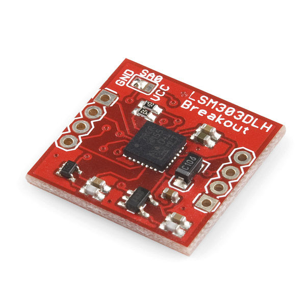
LSM303 Breakout Board - Tilt Compensated Compass
Replacement:SEN-10703. We've added components to the new version of this board to address concerns about voltage translation on the SDA and SCL pins. This page is for reference only.
The LSM303DLH is a triple axis accelerometer combined with a triple axis magnetic sensor. This breakout board uses the LSM303DLH to give a you the data you need to feed into a microcontroller and calculate tilt-compensated output.
- +- 2/4/8 g dynamically selectable full-scale
- +-1.3 to +- 8.1 gauss magnetic field full-scale
- 16-bit data out
- I2C interface
- Embedded self-test
- Schematic
- [Eagle Files](http://www.sparkfun.com/datasheets/Sensors/Magneto/LSM303 breakout board-v11.zip)
- Datasheet
- Application Notes
Comments
Looking for answers to technical questions?
We welcome your comments and suggestions below. However, if you are looking for solutions to technical questions please see our Technical Assistance page.
Customer Reviews
No reviews yet.
Check this link
(https://github.com/ryantm/LSM303DLH)
It is an Arduino library to read the values for this sensor based on a similar Pololu board. Haven't tried it out but it claims to have a function for computing the tilt-compensated heading for those looking to use this sensor as a tilt-compensated compass.
Pololu has one for the same price, it's in stock, and it has level shifters.
http://www.pololu.com/catalog/product/1250
I don't understand why Sparkfun hooked up the i2c lines to 1.8V as the datasheet clearly states it can be VDD + 0.1V, so it could easily be run at 3.3V
The LSM303DHL is basically a two different ICs (from different manufacturers) slapped together into one package, which makes the datasheet pretty complicated and difficult to understand. If you look at the requirements for the magnetometer's VddIO, you can see that it cannot exceed 2 V, and the voltage on the magnetometer's I2C lines cannot exceed VddIO+0.3V. This is probably why Sparkfun used 1.8 V. It is a shame that they didn't include built-in level shifters or at least break out the regulated voltage lines as this board looks like it is somewhat difficult to use.
Read datasheet again. ;)
Vdd: 2.5V .. 3.3V
Vdd IO A: 1.71V .. Vdd+0.1V
Vdd dig M: 1.71V .. 2.0V
Vdd I2C Bus: 1.71V .. Vdd+0.1V
I use it with a 3.3V I2C bus without problem (and without level converter).
Yes, the above schematic (and PCB too) is wrong.
The good connection: the VDD dig M=1.8V and the others are 3.3V :)
(Fig. 4.: LSM303DLH electrical connection 1 - recommended for I2C fast mode)
Thanks for the clarification. Maybe Sparkfun should redesign this board to make it compatible a with 3.3V I2C bus.
Check the iNEMO schematic from ST, blalo is correct.
http://www.st.com/stonline/books/pdf/docs/16306.pdf
So the I2C bus on this runs at 1.8V. Looking at the Sparkfun Logic Level converter, it seems that it might have problems switching 1.8V logic to 5V logic. Any thoughts?
It seems that the I/O data lines are 3.3v tolerant at least (but need to be confirmed).
For I2C you need bidirectional level shifters, look at this nxp AP note:
http://ics.nxp.com/support/documents/interface/pdf/an97055.pdf
Unfortunately, the data lines aren't 3.3V-tolerant. According to section 3 of the data sheet, the absolute maximum rating for "the input voltage on any control pin (SCL, SDA)" is VddIO+0.3V. VddIO on this board is 1.8V, which means you can't safely apply more than 2.1V to the I2C pins.
Section 2.2 gives 1.8 typical for VDD_IO and VDD_IO < VDD+0.1v
But I agree it's far from being "normal" operation.
Anyway there is some interesting chips from TI/Maxim and others for this kind of level shifting. An idea for a breakout, or as update to this one as 1.8v I2C is not common (mainly targeted for SoC like omap/tegra).
VddIO is the logic supply voltage for the magnetometer and accelerometer, not the allowed voltage on the logic lines. The accelerometer can handle a VddIO up to VDD+0.1V and the magnetometer can handle a VddIO up to 2V (this is probably why Sparkfun just chose to use 1.8V for both). Once you've set VddIO to a particular value, however, you are further limited by that value when it comes to what I2C voltages are considered "in spec", and those are the limitations from section 3 that I quoted.
So sparkfun should have put i2c level converter since this board is really targeted for 5v operation.
It's not possible to add level conversion without adding another 1.8v regulator since 1.8v is not directly accessible.
In this actual form, this breakout is nearly useless for all people using arduino and other microcontroller with 3.3/5v I2C interfaces.
Hunting around, it doesn't look too bad to fix up - MAX3000 bidirectional logic level translator will do anything between 1.65 to 5.5V, so that's fine for the 1.8 to 5V required for *duino operation. A 1.8V voltage regulator is about 30p (MCP1702).
Agreed, SF could have put in some decent level translation themselves, but it doesn't look too painful to fix, just irritating to buy the £4 MAX3002EUP and have the faff of doing SMD soldering. But I'd rather practice SMD soldering with a cheap chip than with a fancy one. Hope that helps anyone!
Is there solution to use IC in DIP package or transistors for level shifting?
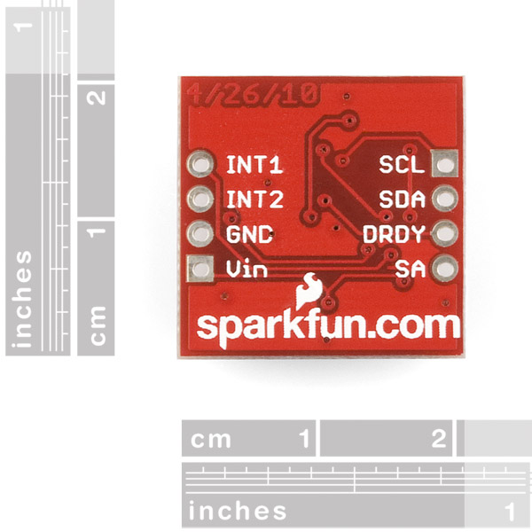
It would be nice on all your I2C products to define a standard that would use the same pinout for SCL,SDA,VCC,GND,INT. I would prefer a single row of 8 pins, instead of two 4 pin connectors. Or, at least put one 4 pin connector with the SCL,SDA,VCC,GND. Thanks
I was trying to find the resolution of the accelerometer of this chip. The data sheet has very little about the accelerometer. Can someone please give more details about the values of acceleration data and what they represent in x, y and z direction. (0g, 1g, 2g..?)
Dear All
I have a question regarding this module, I am kinda new to the sparkfun products and i was wondering if there is any particular requirements or equipments that i need to have before i can configure this module. any feed back i will appreciate it very much
This board needs to be redesigned.
3.3V should be run to the Vdd_IO_a input so at least 3.3V devices can work without level shifters.
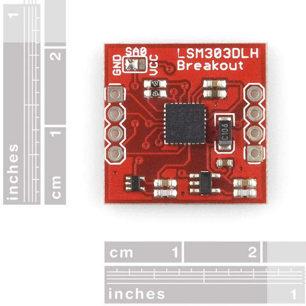
What is the solder jumper GND, SA0, VCC on the breakout board good for?
What is the Vcc for the board? 5v? I see that the board drops the voltage to 1.8 and 3.3 for the chip but I do not see a range for the board input Vcc.
The range for the Vdd is 2.5 to 3.3. You can find this under Electrical Characteristics table in the datasheet. Hope this helps!
Can someone explain why this would be a worse choice than an ADXL345?
My primary use will be the accel, though I was going to eventually want a compass as well. This appears to have a higher precision than the ADXL345 (12 bits vs 10), but maybe the accelerometer on this has less accuracy? ADXL has a 16g scale, but I'm pretty sure 16g would cause my quadrotor to disintegrate so I don't think I'll need that. This doesn't have SDL, but I prefer i2c anyway. The i2c voltage level isn't going to be an issue since I'm also using an ITG-3200 which has the same requirements.
This says 16 bit, but the accelerometer apparently comes out as 12 bit, ADXL ALSO says 16 bit, but for 2g it only operates at 10 bit. ADXL has 4mg/LSB resolution at each setting, this has 1mg/LSB for 2g, 2mg/LSB for 4g, and 4mg/LSB for 8g. So it's FOUR TIMES as precise for 2g applications than the ADXL.
As far as I can tell for an additional $2 I get extra resolution and a compass and no significant disadvantages.
Can this be used to tell when board back to horizontal position?
I just ordered and received one of these boards. I am not sure what all the stink in earlier posts is about - The schematic clearly shows that the I2C lines are pulled up to the 1.8v source through 10k resistors. Proper use of a I2C bus requires one to either pull the lines low (for a 0) or tristate the line (for a high). Most 5v micro's will see 1.8v as a high, so you are all set. The only way to cause problems is to have the micro drive the I2C lines high, which is a no-no as we all know.
Chris, the Mdata will be static if you stop a read in the middle of the xyz registers - the unit will not update if it thinks you are in the middle of a read. Make sure you are starting at the beginning of the x data and reading all 6 bytes to the last byte of the z data (ie instead of reading xx, yy, zz bytes, you may be reading xy, yz, zx or something like that). It is easy to be off by one and jam the updating.
Can you tell me how to use it with an arduino then ? It also freezes when i connect it to 3.3 or 5v , sda and scl to 4 and 5 on an uno
Oops. I hooked the i2c lines to 5V. Is it dead now?
OK, an update. I switched to 3.3V i2c and I'm getting data now. I'm using the above mentioned library and sketches, but the output isn't making any sense.
I'm getting this:
A X: -69.00 Y: 7.00 Z: 1053.00 M X: -134.00 Y: -61.00 Z: -618.00
A X: -69.00 Y: 5.00 Z: 1056.00 M X: -134.00 Y: -61.00 Z: -618.00
A X: -79.00 Y: 5.00 Z: 1051.00 M X: -134.00 Y: -61.00 Z: -618.00
A X: -73.00 Y: 4.00 Z: 1051.00 M X: -134.00 Y: -61.00 Z: -618.00
A X: -74.00 Y: 5.00 Z: 1053.00 M X: -134.00 Y: -61.00 Z: -618.00
A X: -76.00 Y: 7.00 Z: 1058.00 M X: -134.00 Y: -61.00 Z: -618.00
The A values change depending on orientation, but the M values don't.
What am I missing?
edit
I dunno, does it still work? If not, it's probably dead :-)
After a power cycle the magnetometer started working, but I'm getting inconsistent data. Going to assume it's toast. :(
fail board?
I purchased one of these and am having issues with it. The first issue seems to be getting it calibrated as it seems to output a number as high as -4096 on the x_min access and sometimes other accesses.
However taking the number just before that seems to get the job done BUT what you would expect as being North is not in fact North and seems to be about 40 odd degrees off.
I am using the recomended library.
Does anybody know if this gives Euler angles? HMC6343 does that but didn't work with my arduino so looking for an alternative.
Since there seems to be some confusion about how to drive this board, I thought I'd post my soloution here.
I used the sparkfun level shifter with the Arduino Nano (5V) and had no issues. Only trick is the level shifter needs a 1.8v power supply to avoid damaging the compass chip. Hence I had to tap a wire to the breakout board.
Photo and information here:
http://www.flickr.com/photos/38462165@N05/5474598509/
So that people who read this in the future know,
This will work with an Arduino Uno. I used the BOB-08745 level shifter with a voltage divider to drive the i2c lines. Using the library for the Pololu board I can get heading information
Just checking, but anyone have any idea on when it'll be restocked?
Anyone know of something similar at similar cost that is practically plug & play with arduino? I want something like this, but I have very little experience with electronics. That's why I use arduino. It'd be cool to get something like this work for someone like me with little experience.
Did you check out the Arduino library for the LSM303 linked in an earlier comment? It has code for getting the tilt-compensated heading (so you don't have to do the math yourself), and it links to an alternate carrier board for the same sensor IC that has level-shifters built in, so the I2C lines can be plugged directly into an Arduino without the need for external level-shifters and extra voltage regulators.
I thought someone said that they had issues of frying it if it had more then 1.8v in on it. (Also, just as another comment... can you add a function that emails people when there is a reply to their comments specifically? I didn't have a clue there was a reply to this... and you replied 5 days ago. At least a checkbox for people logged in to have it send notifications.)
Which "it" are you talking about? Sparkfun's board could die if you connect the I2C lines to more than 2.1 V (I haven't tried it, but the datasheet says that this would be out of spec for the board). The Pololu board this arduino library was written for has built-in level shifters that allow it to be directly connected to parts running at the same voltage used to power the board (e.g. 5 V) without being out of spec.
bzerk:
Best application note ever.
Aw man, you design a whole product around a Freescale 3-axis Digital Accelerometer and a Honeywell HMC5843 Magnetometer, then a couple of months later you can buy a single chip combining both of these for less money - I can't keep up!
I would love to see the bare IC available as well!
Why do companies like ST and Honeywell call sensors like these compasses? This really frustrates me!
Is it because they have a specific magnetic field sensitivity or do they just do it as some marketing gimmick?
I'm kind of confused by your comment. If you look at ST's datasheet for the part, they never call it a compass (that's SFE's name for their carrier board). However, it is a magnetometer with the appropriate sensitivity and it can tell you the direction of the Earth's magnetic field, which is pretty much what a compass does. I'm not all that okay with calling it a "tilt-compensated compass", though, since that implies calculations are being done for you when you actually have to do them yourself (it's like marketing an IMU board as an AHRS module just because a skilled individual could conceivably compute the attitude and heading from the raw data).
Ah, Bob I missed the heading of the ST datasheet. I assumed sparkfun copied the "Tilt Compensated Compass" text from it so I skipped over that part when reading. ST's datasheet title of "3-axis accelerometer and 3-axis magnetometer" is accurate to me.
Honeywell's datasheet for the HMC5843 on the other hand is a different story. They call their 3 axis magnetometer a "3-Axis Digital Compass IC"... but it doesn't output degrees or pitch which is what I would expect. Before reading your comment I assumed ST was trying to claim the same thing as Honeywell.
If an IC outputs magnetic field strength, it should be called a magnetometer... if it outputs heading in degrees, then it can be called a compass IMO.
macpod:
Just purchased one of this. Can't wait to see how it works.
I Just read the data sheet and unless I'm incorrect the tilt compensation has to be done outside of this sensor. The data sheet indicated that the LSM303 has to separate sensors inside it's body they even have different addresses. The only output registers are for the accelerometer and magnetometer.
This sensor is still extremely useful it provides a cheaper alternative to the HMC5843 (intill the HMC5883 comes out), and it would be simple to implement tilt compensation on a uC with this sensor.
I am interested in this unit but don't know much about these.
Would someone be able to compare this unit with the HMC5843 magnetometer (http://www.sparkfun.com/products/9371) primarily to give advantages one has over the other?
Look more on the web...seems Honeywell is using ST Micro's production facilities for the HMC5883. I presume there was some IP sharing, so the LSM303 is probably functionally the same as the HMC 5883. I suspect, however, the ST Micro chip will be less cost, as ST Micro has consistently gone for the high volume applications.http://edageek.com/2010/01/08/honeywell-hmc5883-sensor/
If you want to drool over another Magneto/ Accelerometer, check out Freescale's MAG3110 upcoming offering - http://www.freescale.com/webapp/sps/site/prod_summary.jsp?code=MAG3110
Based on the product description I thought this would output a tilt compensated compass heading over I2C. However, it does not. It gives you the 6 raw values you need, but it is up to you to do the non-trivial math. Still, this is a great price for a digital 3-axis accelerometer and magnetomer.
It's very high on the build schedule, barring glitches I'd expect them within a week. (And note our "Autonotify" button on the product page, which will send you an email when they're back in stock.)
What about the L3G4200D 3-axis gyro also from ST? Either the L3G4200D or IMU3000 will make a pretty powerful low-cost two chip IMU.
Sweet. its gonna be in my next big order!
update: they give you raw values and a lot of math. drat.
Will there be a board with this and the IMU3000? That would be nice for dead reckoning.
Finnaly compass with titlt compensation for under 30 bucks!
BTW: When is this going to be in stock?