- Home
- Product Categories
- 3-axis
- SparkFun Evaluation Board - ADXL345

SparkFun Evaluation Board - ADXL345
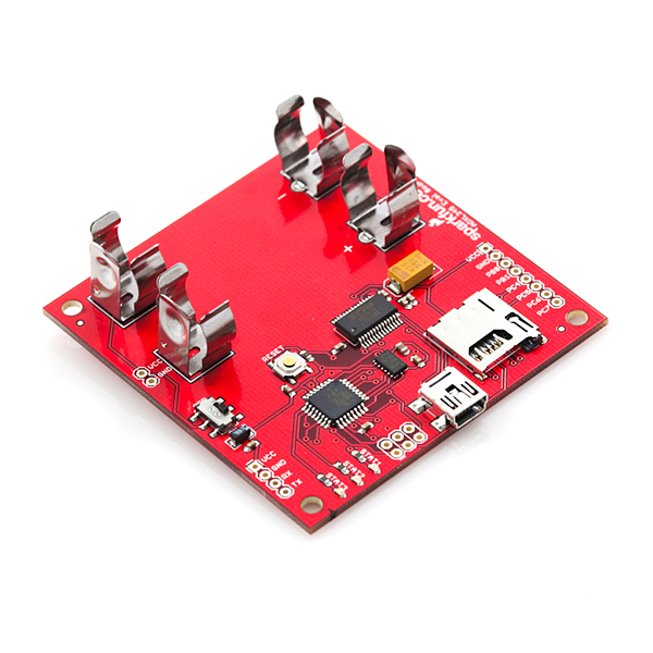
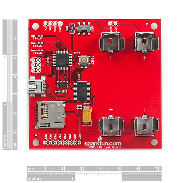
This is an evaluation board for the ADXL345 three-axis MEMS accelerometer. The ADXL345 is an awesome little accelerometer, capable of measuring acceleration of up to ±16g at up to 13-bit resolution. The evaluation board includes everything you'll need to adjust the ADXL345's settings, and monitor and log its outputs. The on-board ATmega328 takes care of all the I2C/SPI communication with the ADXL345, and it will also log the x-, y-, and z-axis acceleration values onto a uSD card.
The board includes a USB interface, which allows you to read/write any of the ADXL345's registers using a terminal emulator. The default baud rate is 57600bps (8-N-1). The UART pins are also broken out allowing a direct TTL interface with the processor. Power can be supplied by 2xAA batteries, or with a 3.0-3.3VDC power supply at the VCC/GND pins.
The ADXL345 evaluation board does not include batteries, uSD card or a USB cable, check the related items section below for these products. The source code provided below is written in C and bundled with hex files ready to load, however we've also made an Arduino sketch available that returns values from the ADXL345 so that you can take advantage of the Bootloader. The Arduino sketch doesn't do anything with the on-board LEDs but it does operate the accelerometer.
- ADXL345 triple-axis accelerometer installed
- microSD card socket for FAT32/16 data logging
- Arduino bootloader "Lilypad Arduino w/ ATmega328"
- USB connector for serial communication
- 2xAA battery sockets to power board
- Pre-installed firmware logs ADXL345 outputs and allows you to read/write registers via USB
- 2.75x2.70"
SparkFun Evaluation Board - ADXL345 Product Help and Resources
Core Skill: Soldering
This skill defines how difficult the soldering is on a particular product. It might be a couple simple solder joints, or require special reflow tools.
Skill Level: Rookie - The number of pins increases, and you will have to determine polarity of components and some of the components might be a bit trickier or close together. You might need solder wick or flux.
See all skill levels
Core Skill: Programming
If a board needs code or communicates somehow, you're going to need to know how to program or interface with it. The programming skill is all about communication and code.
Skill Level: Rookie - You will need a better fundamental understand of what code is, and how it works. You will be using beginner-level software and development tools like Arduino. You will be dealing directly with code, but numerous examples and libraries are available. Sensors or shields will communicate with serial or TTL.
See all skill levels
Core Skill: Electrical Prototyping
If it requires power, you need to know how much, what all the pins do, and how to hook it up. You may need to reference datasheets, schematics, and know the ins and outs of electronics.
Skill Level: Rookie - You may be required to know a bit more about the component, such as orientation, or how to hook it up, in addition to power requirements. You will need to understand polarized components.
See all skill levels
Comments
Looking for answers to technical questions?
We welcome your comments and suggestions below. However, if you are looking for solutions to technical questions please see our Technical Assistance page.
Customer Reviews
No reviews yet.
I recorded a lot of data using this accelerometer.I have around 750,000 data points. I did set the Accelerometer to +/-4G before i started recording. Can anyone tell me "In 1 second, how many data points get recorded" ? That way i can correlate the Acceleration vs Time.
Is there a way to communicate with multiple ADXL345 on the same I2C bus?
Thanks!
Hello All, I am planning to use this Accelerometer on a device to measure Vibration. The question i have is "Can i put the Accelerometer inside a Ziplock bag ? By any chance, if the batteries heatup, is there a chance that the Ziplock bag can catch fire ?
Nope, mostly because plastic bags just melt and don't catch fire. But why would the batteries heat up to the point of melting plastic? The accelerometer and/or SD card won't pull that much power. If you shorted the batteries its possible (so don't short the batteries). In other words when working with electricity you should always be careful, but as long as always a few precautions should prevent problems.
Thanks for your reply.
Hello All, I used this Accelerometer to capture Vibration Data. For example, in X-Axis the value is fef6, in Y-Axis the value is 22 and in Z-Axis the value is fff6. Now i have converted this data as per "nuFcrapS - The simplest way i found". After converting, how i do i get meaningful Acceleration G values. Can someone please explain this in detail ?
Hello, hoping someone can help me out here.
I'm trying to set the accelerometer into 3200 Hz, right now I have the BW_RATE register set to 00001111, which according to the datasheet is 3200 Hz. I've tried other frequencies, which have all worked. My baud rate is 57600.
Am I missing something? Is it possible the board will not allow 3200 Hz?
Any help would be greatly appreciated,
Thanks
Guess what happens when you accidentally short the batteries whilst the circuit is plugged in...fried eggs! Note to anyone who has purchased this: when not in use, remove the batteries and SD card, save you destroying 4GB worth of data and $50 worth of circuitry big sigh
I am trying to change the firmware so the accelerometer is in the +/-16G range. I am having problems compiling the code into a hex file. How do you create a new project in AVR Studio, import all the code, and then write to hex. I can load the Hex and EEprom to the device no problem with a STK500. I am not that familiar with makefiles, but I did modify a makefile to work with the stk500 programmer, and then used cygwin to try and compile, but I just get lots of errors. Any help?
If you're on windows, and you've installed AVR Studio, the install should have given you a command prompt option. If not, you need to add the path to you gcc-avr compiler to your system path. once that's all up and running, you should be able to go to the folder in cygwin and type "make clean" to get rid of any previous hex files, then "make all" to compile your new hex file. Hope this helps
Hello,
i want to operate 3 of those evaluation board in different locations. Is there a easy way to simultaneously start and stop these? For example with a trigger pulse through a wire?
Why am I getting FFFF (65536) values? Isn´t it supposed to be just 10-13 bits? Thanks
Ok I got it. The Ev. Board came configured with a 10 bits resolution and +-2g acc range. If the acceleration values are in the FFFF range it means it is working on the negative direction (For example in the X axis: FF = - & FF = 255 => -255). So I created a Matlab script that handles this, if the value starts with FF just consider the second two letters and add multiply by -1, if it doesn't start with FF just consider the whole value, then multiply this values by (4)/2^10 to get it in gravity values (g's), where 4 = +-2g and 2^10 is the resolution of the data. Good luck!
The negative numbers are probably in a format called Two's complement, which is a convention for storing negative numbers as binary. In two's complement, if the most significant bit is set, the number is negative. To get the magnitude of the negative number, you invert it and add one. e.g.:
i bought this evaluation board, and i have a serious problem... after running board, state LEDs turn on and off two times, then 3rd STAT light (yellow light) turned on continuously and does not turn off... SD cards being failed ! and when connect board to computer, commands run and board react normally, but no logging data appeared.... Help me please..... so thanks.
I don't know if this is the solution to your problem but I ordered a card and SD chips from here and they didn't record any data. I am running a Mac and I reformated the SD chips using the disk utility and everything worked correctly. It appears the SD chips sold here have some strange formating that doesn't work with the software. I have chips from another source but haven't tried them yet so they are an unknown.
I'm looking for an Arduino software implementation of SPI, specifically for this evaluation board using Pins Analog 0 through to Analog 3. Any thoughts or links? (or better still example code, the Arduino sample above does not work with this board as the ADXL345 is connected via a different pins)
at what time does the logger record data, every second?
User Guide http://www.sparkfun.com/datasheets/Sensors/Accelerometer/ADXLEvalBoard%20User_Guide2009-09-14.pdf Page 2 "The accelerometer is initialized to log data at 100 Hz with +/- 2g range."
Hey Everybody,
I'm having trouble getting the data from my ADXL345 into a meaningful format. Currently, whenever I try to open the output .csv file with excel I get three columns of gibberish like, 'ff0a, 00f5, ffaa, etc.' Any help y'all have would be g r e a t l y appreciated!!
Have a good one, D
Each column is data from one of the three axes and each word is a hexadecimal ascii representation of the acceleration value. To decode this, capture the data into a text file and then read it into Excel. Refer to the post above that starts with "The simplest way I found" and write back if that's not clear enough.
What version of AVR studio was used to build ADXL345_Eval_v16.hex? Is all of the code needed to build ADXL345_Eval_v16.hex in the file ADXL345_Eval_v16.zip (or included with AVR Studio)?
other times uploading HEX fiel gives:
avrdude.exe: AVR device initialized and ready to accept instructions
Reading | | 0% 0.00s avrdude.exe: arduino_read_sig_bytes(): (a) protocol error, expect=0x10, resp=0x90 avrdude.exe: error reading signature data for part "ATMEGA328P", rc=-3 avrdude.exe: error reading signature data, rc=-1
the response is always the same: resp=0x90 what should it be?
thanks to all kind of help
dear all, I have a lot of problem with this demo board: - serial connection won't work properly: seems that the board TX data at 57600, 7,N,1 but it accept command at 8,N,1! So command "R 00" return "Invalid Command" - if I reply in 8N1, it responds, but it's almost unreadable: "Reg. Addòåó³º Š¢µ·ž®±´½±ž±™…„ž" the board seems to be BROKEN !!!!
So I decided to upload the HEX file. but upload won't work, too: it stops each time in different position. SEEMS ARDUINO BOOTLOADER NOT PRESENT! But I am new with arduino. Should it be?
avrdude.exe -C ..\etc\avrdude.conf -carduino -patmega 328p -P com5 -b57600 -v -Uflash:w:ADXL345_Eval_v16.hex [....] Programmer Type : Arduino Description : Arduino Hardware Version: 2 Firmware Version: 1.16
avrdude.exe: stk500_getparm(): (a) protocol error, expect=0x14, resp=0x90 Vtarget : 0.0 V Varef : 127350018.7 V Oscillator : Off SCK period : 0.1 us
avrdude.exe: AVR device initialized and ready to accept instructions
Reading | ################################################## | 100% 0.02s
avrdude.exe: Device signature = 0x1e950f avrdude.exe: safemode: lfuse reads as 0 avrdude.exe: safemode: hfuse reads as 0 avrdude.exe: safemode: efuse reads as 0 avrdude.exe: NOTE: FLASH memory has been specified, an erase cycle will be perfo rmed To disable this feature, specify the -D option. avrdude.exe: stk500_cmd(): protocol error
I would like to actually use this as a 3-axis accelerometer data logger. Obviously it won't do this out of the box. Any suggestions?
From the description "The evaluation board includes everything you'll need to adjust the ADXL345's settings, and monitor and log its outputs. The on-board ATmega328 ... will also log the x-, y-, and z-axis acceleration values onto a uSD card."
What is it you're missing?
Hello, I am a researcher, I bought a card ADXL345 Evaluation. The software loaded is lost. You can send me a copy of the software and directions on how to upload? thanks Giuseppe Morello
Hi, I run the processed described by you, and it says it "system wide configuration files - avrdude.exe: can not open config file" ": Invalid argument - avrdude.exe: error reading system wide configuration file "" How can I fix it? thanks
For those that have overwritten the factory software image, here is a simple walkthru to get the factory image back on the eval board using Windows xp/7:
That's it... Now you should be back to the factory image and able to record accel values to the sd card.
Thanks, Zeb
I have my board spewing data through CoolTerm on my Mac. Read the UserMan... I can stop the data stream by pressing any button, as the doc explains, but I cannot restart the stream by pressing 's' (as the doc explains). I also can't execute read and write commands. I type a command in, and I get a carriage return in the terminal, but nothing happens. I'm running the correct comm's setup and have FTDI drivers installed.
Has anyone else encountered this problem? Thx.
OK, I figured it out. I added a 3ms Transmit delay and made sure Terminal Key Emulation was CR only (not CR+LF, not LF). Now it works through the terminal emulator as described in UserMan (aka doc).
For those wanting some Arduino code for this board based on the breakout board tutorial, check out this.
Hi i am just wondering. Since the board is using USb. How to connect it to arduino board and used the arduino code?May i get the circuit schematic connection between arduino and evalboard from you?thanks
The eval board is an Arduino! :-) It runs the Arduino bootloader and has an onboard USB-Serial connection implemented using an FTDI chip. In addition, it has the accelerometer and all associated circuitry mounted on the board, along with AA battery contacts and a micro SD card slot.
All you have to do is make sure you have the Arduino IDE installed and then plug in the board via USB to your computer. You should then see a new serial port available to upload to in the IDE. Select "Arduino Duemilanove w/ATmega 328" as the target board, paste the code from my pastebin into a new sketch and hit upload. Voila! If you now open a serial monitor window set to 9600 baud using the same serial port you just uploaded to, you should see acceleration values being reported back.
I buy the Evaluation Board recently, and i can change the ODR by burning BW_rate of register.I have a trouble that the ODR couldn't modify over 200Hz, but i need use it to measure mechanical vibration for 3200Hz. Do you have any idea to change the ODR for 3200Hz?
Hello. I don't know where I could ask this question.
I am investigating ADXL346 as I really like the orientation functionality. However, the interface level is 2.75 volt max. Does anyone know why they would design something like that? I have never seen any MCU works at that voltage. My chip works at 3.3V and that makes it really hard to interface.
Thanks in advance.
Lower voltage equals lower power consumption, so VCCs are headed in that direction (many Atmel chips work down to 1.8V). You can use voltage translation circuitry to interface anything to anything else, but given the extra hardware, it might be easier to just change the orientation in software.
Nice little board.
But how do you use the data>??? OK, it logs to an uSD and there is tons of available data in 2's compl. form. I need to draw a graph of that... and changing each value at a time is not an option.
Any suggestion on how to create the graphs for each axis?
Thanks a lot!!!
The simplest way I found was to use a spreadsheet program like Excel and use the built-in function hex2dec(). You may need to follow that up with an if() to do the two's complement adjustment, as my Excel didn't seem to recognize negatives.
e.g.
A1 contains fffd
A2 contains =hex2dec(A1)
A2 shows 65533
A3 contains =if(A2>32767;A2-65536;A2)
A3 shows -3
When plotting, you may also want to calculate the absolute magnitude of the three channels by squaring the signed decimal value of each channel using =power(), summing all the squared values and then taking the square root using =sqrt().
nuF
Thanks...this is a very helpful post, which explains how to quickly interpret the data, and is not found in any of the docs. Had a plot in 10min.
Thanks for a great board and especially for sharing the schematics and code. I'd like to share some novice gotchas:
1. Beware of the Pocket Programmer and its 'Power Target' switch which will apply 5V to the board. While the '328 doesn't mind, the ADXL345 has an absolute maximum rating of 3.9V. I feel lucky.
2. Beware of the labels on the header socket JP1 - the signals labelled 'PC6' and 'PC7' go to ADC6 and ADC7 on the 328P and not to PORTC. Although there is a PC6, it does not come out on the header (you can't use it anyway because it's shared with !RESET) and there's no such thing as PC7.
nuF
Beware that the ADXL345 is interfaced as an SPI device, SPI is bit banged because the hardware SPI is dedicated to the micro-SD care. No idea why they did it this way, but whatever...
I added I2C support by tapping into the traces off the mcu and running two jumper wires over to the .1" port output. Just make sure PORTC bits 1:2 are set to input mode!
I have finally started communicating with my board. But, my data coming out many times is in the 65,000 range. I can have 2 axes working fine, and the 3rd is saturated (like FFF4 and other nonsensical numbers). Any thoughts? Am I reducing the data wrong?
Does anyone know the clock speed of the atmega328p on this board? I can't seem to find it in the documentation.
i believe the STK500V1 boot loader is set for 8mhz clock. So, it should be 8mhz.
I have a problem communicating with the board.<br />
<br />
I am working w/ Windows XP. I have loaded numberous Virt com port drivers. I loaded teraterm. <br />
<br />
I can't figure out how to get the board to be recognized<br />
<br />
What virtual com port drivers should I use (free hopefully)<br />
<br />
Any help is appreciated
Did you download the FTDI drivers?
I got data off the board, but it looks like it is hex. I thought the units were voltage. Where am I wrong? Please help, I'm just a dumb mechanical guy
"dumb mechanical guy" is an oxymoron.<br />
<br />
The output is the raw 10-bit data from the accelerometer. You'll want to check out the datasheet for the ADXL345 (follow the link to the related product). You'll find out that the raw data is output as a 2's compliment number; basically a number that can represent positive and negative numbers. Depending on the range you've selected for the ADXL345, you'll have to scale this number appropriately to come up with the number of g's.
I jsut plugged mine in and looked at the data. It looks like a combo of hex and decimal output. Any thoughts?
I just pulled my board out and it has no reset button as advertised. Any help?
Pin 1 on the ISP header is marked with a little bar. It is closest to the LEDs.<br />
<br />
To write the .hex file included in the source code zip, you can use this (assuming your board comes up as /dev/ttyUSB0):<br />
avrdude -carduino -patmega328p -P/dev/ttyUSB0 -b57600 -v -Uflash:w:ADXL345_Eval_v16.hex<br />
<br />
Please note that the above avrdude cmdline does the programming over the USB connector, not the ISP connector with an external programmer.
Anyone coded in Arduino for this board? I appreciate if you can share.
Thanks for the reply. I am just curious. Why didn't you guys code it in Arduino in the first place? <br />
<br />
I suggest you put a caution in the user guide. I just read the user guide, got excited, downloaded Arduino IDE, and erased it right away before I realize how catastrophic that was. Since I don't have an ISP. I have to figure out how to port the c code into Arduino. Communication with ADXL345 is no big deal but microSD and FAT32 are big problems.<br />
<br />
<br />
I for one am glad it's not programmed in arduino.
Can you please provide an arduino template for this board?
As it is now I can program the board with arduino but I am having troubles accessing the accelerometer and the sd card.
Thanks
Can you give a brief description on how to use the pocket avr programmer to upload a script on the board. The board doesnot say which end is the first pin of the 6 pin header, can you put some light on it. If possible can you give the command line to be written for avrdude to write the source code (the one provided on this page) to the board. I tried a number of things but it keeps saying initialization failed.
( Sorry if any of the above is too obvious... I am a newbie)
KD, please see my separate comment that answers your questions.
I didn't see a low-pass, anti-aliasing filter on the schematic or a place on the board to put one in. Did I miss it or is it built in, somehow, to the accelerometer?
The ADXL345 is a digital accelerometer that does not have the option of adding any analog filtering for anti-aliasing. You could add your own digital filtering, the application note AN-1025 describes using the FIFO Buffer to reduce the u-controller poling rate while maintaining the advantages of having a higher sampling rates in the device.
The source code doesnot seem to have code for Arduino ( I think its for avrdude). Can you please post the code using Arduino.
The source code provided is all we have, sorry! There is (and never was) specific code written in Arduino, just C.
Damn it. I just programmed using Arduino IDE. Does it mean that the original program was gone?
AVR Studio + AVR MKII
Yes. You wrote over the original code.