- Home
- Product Categories
- Components
- Luxeon Rebel LED Tri-Color Driver

Luxeon Rebel LED Tri-Color Driver
Replacement: None. We are no longer carrying this LED driver in our catalog. This page is for reference only.
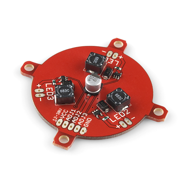
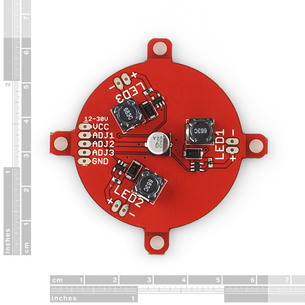
Here is a driver board based on the ZXLD1360. It has three discrete channels allowing for control and blending of three individual LEDs. This is made to mate with the Luxeon Rebel breakout boards.
Each LED driven to ~650mA with adjust pins open, off when adjust pins grounded.
Note: PWM control must be with an open pin (PWM high) or ground (PWM low). Do not pull the adjust pins high unless you want to drive the LEDs at greater than 650mA. The adjust pin on a ZXLD1360 driver chip causes the current to be off when it's held low, and on when it's open (or hi Z). Driving the pin at a DC level will cause the current regulation to be something other than the 650mA that the open adjust pin will regulate to, possibly much higher. Tread lightly if you don't know what you're doing.
- Datasheet (ZXLD1360)
- Schematic
- [Eagle Files](http://www.sparkfun.com/datasheets/Components/LED/SMD/Rebel 3-pack Tri-Color Driver v10.zip)
- Tutorial
- Sample Code
Luxeon Rebel LED Tri-Color Driver Product Help and Resources
Core Skill: Soldering
This skill defines how difficult the soldering is on a particular product. It might be a couple simple solder joints, or require special reflow tools.
Skill Level: Rookie - The number of pins increases, and you will have to determine polarity of components and some of the components might be a bit trickier or close together. You might need solder wick or flux.
See all skill levels
Core Skill: Programming
If a board needs code or communicates somehow, you're going to need to know how to program or interface with it. The programming skill is all about communication and code.
Skill Level: Rookie - You will need a better fundamental understand of what code is, and how it works. You will be using beginner-level software and development tools like Arduino. You will be dealing directly with code, but numerous examples and libraries are available. Sensors or shields will communicate with serial or TTL.
See all skill levels
Core Skill: Electrical Prototyping
If it requires power, you need to know how much, what all the pins do, and how to hook it up. You may need to reference datasheets, schematics, and know the ins and outs of electronics.
Skill Level: Rookie - You may be required to know a bit more about the component, such as orientation, or how to hook it up, in addition to power requirements. You will need to understand polarized components.
See all skill levels
Comments
Looking for answers to technical questions?
We welcome your comments and suggestions below. However, if you are looking for solutions to technical questions please see our Technical Assistance page.
Customer Reviews
No reviews yet.
Alrighty
I have a few questions that would be useful to have posted for reference. I am designing a lighting system based on the zxld1360 but i need 5 drivers instead of three. In all other respects it will be the same as the above system.
So... what is the part number for the inductor you are using and why is R1 47uF instead of 4.7uF as shown in the suggested usage in the datasheet for the zxld1360? And also why is L1, the inductor, 68 uH rather than the 47uH as shown, once again, in the datasheet?
These would be helpful to know and may make modification easier in the future.
If smoke comes out, due to connecting PWM control to Arduino PWM, would the replacing the ZXLD1350 driver chips be the most likely fix? Or would the inductors be the likely problem? Does anyone have experience fixing their mistakes with this board?
I plan to order both the inductor and driver,, but of the two parts, the inductor looks like the more difficult part to replace. I'll post an update if I manage to fix the problem. Thanks! -John
Hey guys,
I was wondering if these will work with these LED Rings http://www.superbrightleds.com/moreinfo/led-headlight-accent-lights/led-angel-eye-headlight-accent-lights/49/
Thanks, JVarhol
For those of you who don't want to do an annoying transistor to drive each channel of this baby, just do a simple resistor voltage divider with high-ohm resistors.
I used from the arduino out pin a 10k in series with 3k to ground. Using voltage divider math Vout (across the 3k resistor)=5v(3k/(10k+3k))=1.153v, low enough to avoid sending out more current than the ZXLD1360 can handle.
so with just 6 resistors you can now control this simply from the arduino out pins. Here is a schematic:
http://www.northstreetlabs.org/rebelfix.jpg
Guys I think this is a great driver board, if you included some SMD resistors into a newer revision to work with the arduino, and dropped the price a little (these drivers are pretty cheap) it could sell a lot more often, I am using it to drive a 10W RGB LED and it works wonderfully!
I am completely confused...
I have just purchased one of these boards but I have yet to power it on. I have been looking at how to control it and I just can't make any sense. My intent was to control the LEDs with an arduino through PWM, but the example code appears to be for avrdude only and is unintelligible and the datasheet isn't telling me anything I understand.
Is it even possible to control this driver using the PWM output from an arduino? If it is, how do I control it? Do I need to add this magical transistor that I keep hearing about and how does that even work?
Thanks
p.s. get some example code in .txt
See the earlier comment from SpikedCola. You'll want to use a small NPN transistor between the Arduino's PWM output and the ADJ pin on the driver.
The Arduino's PWM output basically involves switching a voltage on and off. But the ADJ pin on these LED drivers needs to be connected to ground to switch the LED on. The Arduino will switch the transistor on, and when the transistor is on, it connects the ADJ pin to ground.
Would be nice to have a parts list. I'm a beginner and would like to design the PCB myself. I don't have a clue however on what parts to source, there are so many variables. Maybe Sparkfun could stock the components, or setup some kind of affiliate deal with Future electronics. Just a thought.
could you adjust the brightness of each led with a simple var-resistor?
Where does the price on these come from? The ZXLD1360 appears to be $1.85/ea in small quantities. I can understand some overhead and markup, but these boards seem like they should go for about half what you are charging.<br />
<br />
And as long as you are designing it to mate with your luxeon RGB breakout, I think it'd make sense to have a variant with the LEDs on the same board... That, I'd pay $50 for.
Alternatively, you could submit the board itself to batch pcb, and order and assemble the components yourself (unless I'm missing something) since the layout is attached in the eagle files.
A simple fix for the ADJ pin problem (and also the Arduino PWM problem I suppose) is to use a small NPN to drive the ADJ pin, as so:
http://skoba.no-ip.org/adj_fix.png
(image taken from a similar drivers' datasheet)
I sent this off to Pete a few days ago but figured Id post it here too, just in case!
For a newbie, what would be a "small" NPN in value or typ?
Link: NPN Transistor
I was just coming on to ask if that same idea would work! :)
SF can you test that solution? If it works maybe it could be added to the V2 of he board to allow 0-5V PWM?
Yes, it will work, and that's the plan for the next rev.
When is the next revision due? I am interested in buying a few of these, but I don't want to wait too long.
I contacted SparkFun support. They said there isn't a revision planned for the board.
Cool!
Any chance of making this "play nice" with the Arduino PWM? I mean most PWM routines swing between 0-5v; that I have seen on any uC.
Not with the hardware. You can compile and run the example code on an Arduino, but you just can't use the PWM in the Arduino IDE. It will pull the pin high, which causes some problems.
Perhaps using a tri-state buffer between the arduino pwm output and the driver (tri-stated when arduino pwm goes high)?
Will the schematic be available at some point?
Yes! I accidentally forgot to add it. Schematic and Eagle files are up.
Folks,
Have I lost one of the few clues I had left, or is there a typo near the bottom of Page 15 of the datasheet? It seems to me that "x Rs" should be "/Rs". Making such a change would appear to be consistent with Ohm's Law, as well as with the remark in the text that Rs must be increased to limit the total current.
Also: Strictly speaking, the "1.25" in that same equation should be "1.25 V".
TIA,
Eric
I think the datasheet is correct. I just glanced at it, but depending on how the circuit works, it might not have anything to do with Ohm's law. It says:
"Note that 100% brightness setting corresponds to VADJ = VREF"
And in the circuit, Rs is connected to ground. So Rs needs to be large for VADJ to be away from ground. If Rs were zero, VADJ would be grounded, and you'd have zero current flow.
Its not tough to build a circuit that puts out more current the higher you adjust a resistor. You basically just invert the behavior of things somewhere along the way. That seems to be whats happening here. Ohms law can't be applied to things like that.
-Taylor
Taylor,
To which "resistor" are you referring? On page 15, I see a variable DC voltage supply, but no resistor.
On page 1, Rs is shown, but it's not connected to ground.
TIA,
Eric
@esklar81 - yes, you are correct. See the equation at the top of that page. Aside from equations, note that the resistor is in series with the led. Obviously, the current has to be inversely proportional to the resistance. Imagine the resistor going to say, 1MegOhm. The brightness(ie current) is going to go towards zero.