- Home
- Product Categories
- Kits
- Simon Says - Surface Mount Soldering Kit

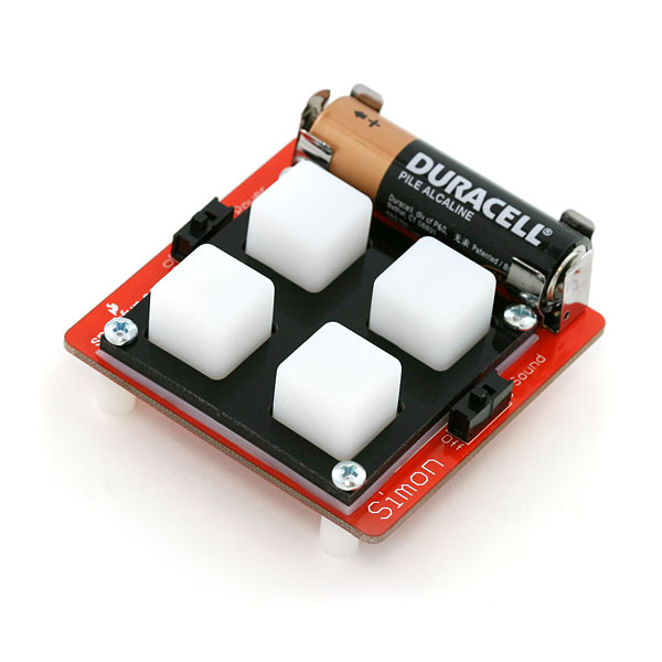
Simon Says - Surface Mount Soldering Kit
Replacement:KIT-10935. The new version of this kit has a lot of tweaks that make it easier for someone who doesn't have a lot of surface mount soldering experience. This page is for reference only.
The new version of this kit adds extras of the small components to help you out if you misplace a super tiny resistor. It also has small corrections to the manual and better instructions. This is a kit of loose components that go along with the SMD Soldering Lecture. This is considered an intermediate kit for people who have soldered before and wish to learn how to solder surface mount components. This kit does not include a programmer or a battery. You will need an external programmer to program the firmware onto the ATmega328. All parts are listed below.
Please note that this is now shipping with the 328. This IC is pin compatable, and interchangable with the 168. You will need to modify the make file to reflect this change.
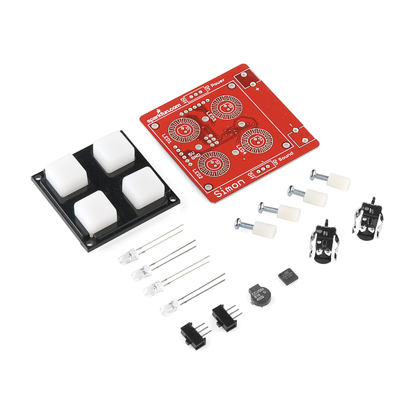
Through-hole components:
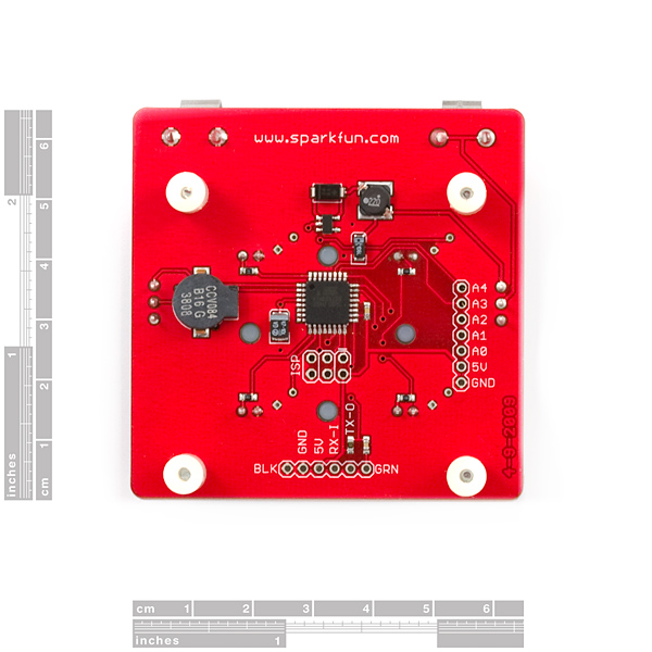
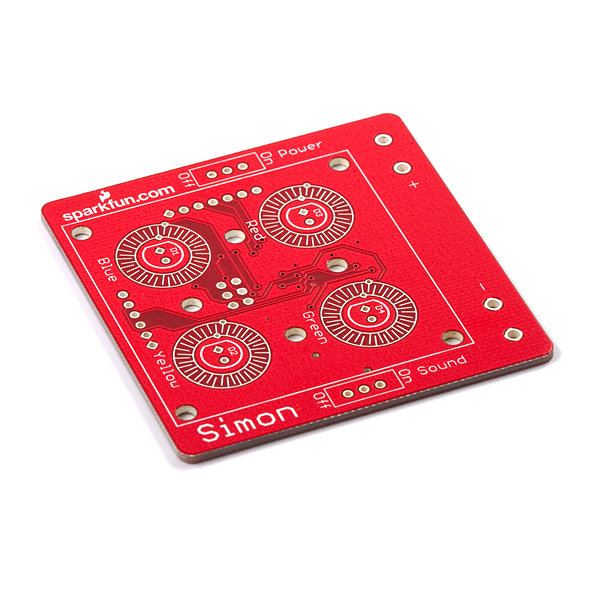
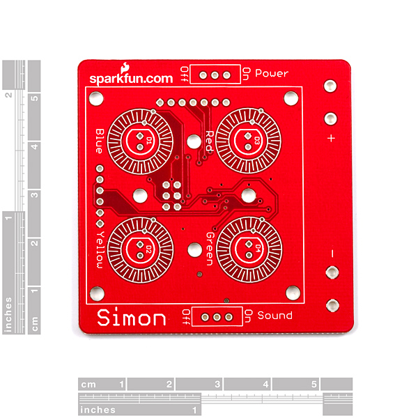
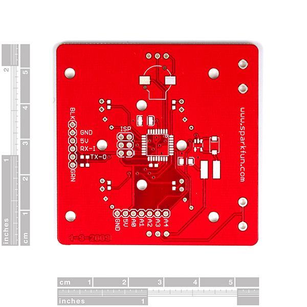
- 1 x ATmega328 based Simon Says PCB
- 2 x AA Battery Clips
- 2 x Slide switches
- 4 x LED (Yellow, Blue, Red, Green)
- 4 x Screws
- 4 x Plastic Standoffs
- 1 x Rubber 4-Button Pad
- 1 x Button Pad Frame
SMD components:
- 6 x 330 Ohm Resistors
- 3 x 10k Ohm Resistor
- 1 x 47uF Capacitor
- 1 x 10uF Capacitor
- 3 x 0.1uF Capacitor
- 1 x MBRA140 Diode
- 1 x 22uH Inductor
- 1 x NCP1400 SOT-23-5 IC
- 1 x ATmega328 TQFP IC
- 1 x Buzzer
Replaces:KIT-08404
- Simon Assembly Procedure (follow the steps! [5MB])
- Simon Board (component print)
- Simon Eagle Files (for trouble shooting)
- Simon Firmware (for programming)
- Simon (Old) ATmega8 Firmware (for programming)
- Simon Schematic (for general reference)
Github Page (Example Code)
Here is some good information for SMD soldering:
SMD Soldering Basics (big 4MB)
- SMD Soldering Workshop
Simon Says - Surface Mount Soldering Kit Product Help and Resources
Simon Says Experiments
October 21, 2010
So you've built up a Simon Says kit? What next? This tutorial will get you up and running with Arduino software, guide you through a few example sketches, and send you on your way to create your own. Careful, this stuff is highly addictive. :)
Comments
Looking for answers to technical questions?
We welcome your comments and suggestions below. However, if you are looking for solutions to technical questions please see our Technical Assistance page.
Customer Reviews
No reviews yet.
This PCB is version '0E' or zero-error. The PCB has zero errors designed into it. We offer versions with errors (2E for example) for those who enjoy troubleshooting and correcting PCB errors.
How many E's can we specify? I'd like about 20,000, and I'm hoping for a Macbook Air. Thanks.
Wot, really? You can add errors to your board? If so, wow. This would really help hone troubleshooting skills. How would one specify how many errors?
He's joking, if you didn't realize.
I need to pick up some SMD skills, and this looked like the perfect way to do it. Will this kit be back in stock anytime soon? (Or do you have suggestions for another good project to start/practice with?)
I have exactly the same question -- had the same thought (good set to practice SMD), and would like alternative suggestions... I signed up for the autonotify, but not knowing how long until these are back in stock, would be nice to have alternatives.
This kit was a great idea for me! Made a custom PCB with lots of SMD chips and components... then figured I'd try this kit first before assembling my board. I've now destroyed 2 components, burned off 2 pads... Good to do this first. Maybe I should stop using lead-free solder...
Wow.. those components are a hell of a lot smaller than i thought they were...
Ok doodle's command line failed for me. I finally got it programed.
./avrdude -c usbtiny -p m328p -U flash:w:/Users/mpechner/Downloads/Simon-v21-Firmware/Simon-v21.hex
No need to the "-B 1" and -U needed.
I used adafuit's tinyUsb programmer using CrossPacl-AVR on the mac.
Yes, the first one I built last weekend is fried. Double checked the solder joint against this second one. It looks good.
Ok. I built a second kit. Still Fail. Even though the instructions say the 328 is preloaded, it does not seem to be.
Looks good?
Michael-Pechners-MacBook-Air:bin mpechner$ ./avrdude -c usbtiny -p m328p
avrdude: AVR device initialized and ready to accept instructions
Reading | ################################################## | 100% 0.01s
avrdude: Device signature = 0x1e950f
avrdude: safemode: Fuses OK
avrdude done. Thank you.
Why the FAIL?
./avrdude -c usbtiny -p m328p -F -B 1 flash:w:/Users/mpechner/Downloads/Simon-v21-Firmware/Simon-v21.hex
avrdude: initialization failed, rc=-1
avrdude: AVR device initialized and ready to accept instructions
avrdude: Device signature = 0x000000
avrdude: Yikes! Invalid device signature.
avrdude: Expected signature for ATMEGA328P is 1E 95 0F
avrdude done. Thank you.
I'll say the bad thing. Will customer support pay attention to this post?
Fried 328? Am I FOOBAR?
Michael-Pechners-MacBook-Air:bin mpechner$ ./avrdude -c usbtiny -p m328p -F
avrdude: initialization failed, rc=-1
avrdude: AVR device initialized and ready to accept instructions
avrdude: Device signature = 0x000000
avrdude: Yikes! Invalid device signature.
avrdude: Expected signature for ATMEGA328P is 1E 95 0F
OY! Did I miss where the description states 402 parts? Ot are these 603 and it has been a while.
A note for those on newer linux or OS X systems:
The code provided uses the older names for AVR interrupts, which won't work with newer compilers. If your board programs, but when you turn it on does nothing except flash the LEDS then:
1. Re-run the compile step (make clean && make all) and you should see an error about an incorrect interrupt name.
2. Change ISR (SIG_OVERFLOW2) to ISR(TIMER2_OVF_vect)
3. Re-run make clean && make all and reprogram the device. It should now work!
corrections
this was a great kit and I enjoy putting it together and programming it. The .hex image worked fine. However, I seemed to have an issue with the c code. The code compiled without error, and uploaded correctly, but the buttons respond oddly, and the lights flash randomly and constantly. As I said, the .hex, pre-compiled version works fine. Any one else have an issue like this?
Hi Chekr, see my comment below. I suspect you need to change the name of the interrupts in the c file.
I just put this thing together, as my first experience with surface mount soldering. Made a couple of mistakes, but I managed to fix everything, yay. I sure am glad I bought a flux pen with this; I did the first few components without it, but once I started using flux, soldering everything (especially that ATmega328) became quite easy! I wouldn't want to do anything like this without it; it seems like a must-have.
The CCV084 buzzer has a resistance of only 16 ohms-- could somebody explain why it's OK to connect it directly between two digital output pins, without a current-limiting resistor? When the buzzer is on, I would think it would draw 5V / 16 = 312 mA, which would damage the ATmega.
It is an inductive load so if you give it a pulse signal its resistance would be much high.
However due to this you must make sure you never set the buzzers pin high and keep it high, or yes it would damage the chip if there is no short protection built in
What programmer could I use with this?
Any programmer that works with avrdude (http://www.ladyada.net/learn/avr/avrdude.html)
For some reason, the ATMega328P that came with the kit had fuses programmed for an external crystal - I had to solder in some leads to the XTAL1 and XTAL2 pins to get it to program. Just in case anybody else gets errors on avrdude, try adding in a crystal to pins 7 and 8 on the TQFP.
The source in Github is not the source used for this board (there is no #define for the 5/3/10 version of the board that I received).
I cant believe it! I didnt think I could do it, but it worked! Sparkfun wasnt lying when they said you could solder this little guy. When I first opened the package and saw how tiny those resistors and capacitors where I said no way. Solder wick is amazing. Thanks Sparkfun for creating the wonderful tutorial and great little kit.
I had a heck of a time getting solder off the MCU pins. I found out there is a dramatic difference in quality between various brands of solder wick. The one I found that worked instantly was M.G. Chemicals Fine Braid Super Wick.
I also had a lot of bouncing on the keys, and could never win the game after I got it programmed. However I was able to fix it as follows (in Simon-v21.c, line 207):
delay_ms(50); // debounce delay added here
if (choice != game_string[current_pos])
{
play_loser(); //Play anoying loser tones
goto BEGIN_GAME;
}
Is there a simple way to find out the correct orientation of the ISP header? I can't see any markings on the board, and the plug on the Sparkfun programmer also does not seem to have markings for correct orientation.
I did determine the orientation from the schematic and a volt meter, but wonder if there isn't a simpler approach? Thanks.
Simple indeed: There's a little rectangular silk-screened blob on the ISP header boundary (like a little ear on the side) - this denotes pin 1. The other easy way is to look at the obvious 5V trace, and check the ISP pinout to know that Vcc is pin 2 of the connector.
Hi all I'm haveing a problem and I can't seem to fix it... I have continuity between my 5V and GND. I have triple checked every thing but still cant seem to fix it. Any help would be greatly appreciated.
-Edit-
I now have no more continuity between 5V and GND. But now I get a very dim blue light.
I already own one of these kits, but I'm seriously considering buying a dozen more, just so I can get my hands on some of those elusive ATMega328P TQFPs.
Is there anyway you could post instructions on debugging? This was my first SMD project and it looks like I did something wrong. I tried to do everything possible to check for shorts or disconnected pins, but everything seems good, however when I try to program it avrdude fails; my programmer works on every other project I have laying around; just not this guy (I bought and built two of them and they both have the same failure). The blue LED pulses when I run avrdude (if that helps debug). Would appreciate any help I could get in getting this working without having to try a third time. They are both 6/3/2009 boards.<br />
<br />
C:\Users\doobie>avrdude -p atmega328p -c usbtiny -B 1 flash:w:C:\Users\doobie\<br />
Desktop\simon\Simon-v21.hex -F<br />
<br />
avrdude: initialization failed, rc=-1<br />
avrdude: AVR device initialized and ready to accept instructions<br />
avrdude: Device signature = 0x000000<br />
avrdude: Yikes! Invalid device signature.<br />
avrdude: Expected signature for ATMEGA328P is 1E 95 0F<br />
<br />
avrdude done. <br />
<br />
Thank you.
I didn't solder pins to the ISP, and turns out after a bit of wiggling the pins it programmed.
I have a couple questions:<br />
<br />
I'm assuming I can load the arduino bootloader onto this, right? (using the ISP connection)<br />
<br />
Once I load the bootloader, how can I program it using the arduino IDE? I'm guessing not directly through the 6 pin connector on the board, at least not with the Sparkfun FTDI adapter.<br />
<br />
Thanks
Yes, you can put the bootloader on it. And you will need an FTDI basic which connects directly to the 6-pin header.