- Home
- Product Categories
- Wire
- JST Jumper 3 Wire Assembly

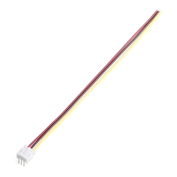
This is a simple three wire cable. Great for jumping from board to board or just about anything else. There is a 3-pin JST connector on one end, bare cable on the opposite end. It also comes with the mating connector for the JST.
- 6" length
- JST connector
- Datasheet
- Illumitune Project (tutorial) (video)
JST Jumper 3 Wire Assembly Product Help and Resources
JST Connector Type
This uses a 3 pin JST PH connector.
Core Skill: Soldering
This skill defines how difficult the soldering is on a particular product. It might be a couple simple solder joints, or require special reflow tools.
Skill Level: Noob - Some basic soldering is required, but it is limited to a just a few pins, basic through-hole soldering, and couple (if any) polarized components. A basic soldering iron is all you should need.
See all skill levels
Comments
Looking for answers to technical questions?
We welcome your comments and suggestions below. However, if you are looking for solutions to technical questions please see our Technical Assistance page.
Customer Reviews
4 out of 5
Based on 2 ratings:
JST Jumper
I purchased an audio amp board that required a JST connector for the channel split, and didn't have any dead cooling fans laying around. These jumpers did the trick and now my powered speakers are up and running.
Ok for what it does, but colors inexplicably changed
Whatever you do, don't pass these to your assembler using the colors to identify where the other end goes. After years of getting them as red-black-yellow, we started getting blue-red-black. Seeing as I printed a few hundred boards using the old pin layout, I now have black to +5v, red to signal and blue to ground. Super confusing to try and maintain :/
No no, you don't understand. This cable is one of the greatest things SparkFun carries! If you've ever tried to make your own cable, you understand how much time this pre-made cable saves. And having the connector attached means you'll be assembling your custom board/project even faster!
Just received "black-yellow-red" not "yellow-black-red" as per the photo, and the layout for Open Segment Display. Buyer beware.
This is the kind of thing that I shouldn't have to deal with in a complicated project. Details count, Sparkfun.
What's the pitch/pin-spacing on these?
BEWARE.... These don't use the standard .1" spacing. They are smaller.
So I get blacks probably negative and reds probably positive whats the white/yellow wire
The colors don't mean anything. This is just a three wire assembly for you to use as you see fit.
Even though it's "just a three-wire assembly", in power scenarios red/black/yellow do have specific meanings. On a standard Molex(-style) power connector, there are four wires: red is +12V, two black for ground, and yellow is +5V.
I agree with you of course, you can use the cable for whatever you wish, but I think it's also important to realize that in certain applications those colors do have specific meanings. :)
Are these in the SparkFun Eagle libeary? Nevermind, Found em, thanks guys your the best.
I can't find it in the library. What is it labeled as?
If you want to add it to your project, enter "jst*" into the search field - should pop right up among results (exact one is probably JST-3-PTH)
If you need to modify it, it's in...
library: SparkFun-Connectors.lbr
device: M03
package: JST-3-PTH
datasheet 404
FYI, the JST connector link is broken.
Sparkfun should start carrying the KR and KRD series from JST. They are compatable with the PH headers (that this cable plugs into) but offer isulation displacement (IDC) instead of crimping wire connections. They would allow for much easier DIY cables, but nowhere in the internet can you buy less than 2000 :(
See http://www.jst-mfg.com/product/pdf/eng/eKR.pdf for more info.