- Home
- Product Categories
- Wireless and IoT
- Bluetooth DIP Module - Rayson BTM-182

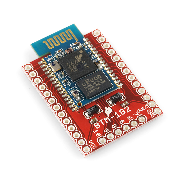
Bluetooth DIP Module - Rayson BTM-182
Replacement:WRL-10253. The RN-42 module is not a direct replacement, however it is a suitable substitute for most applications. This page is for reference only.
Here is a simple breakout board for the Rayson BTM-182. It is an easy to use Bluetooth SPP (Serial Port Protocol) module, designed for transparent wireless serial connection setup. This is a fully qualified Bluetooth V2.0+EDR (Enhanced Data Rate) 3Mbps modulation with complete 2.4GHz radio transceiver. It uses CSR Bluecore 04 external single chip Bluetooth system with CMOS technology and with AFH (Adaptive Frequency Hopping).
The firmware for the BTM-182 is the same as for the BTM-112.
- Class 2 module with PCB antenna
- SPP firmware
- Bluetooth standard Ver. 2.0 + EDR compliant.
- Low current consumption
- Hold, Sniff, Park, Deep sleep modes
- 3.0V or 1.8V operation
- Support for up to seven slaves : SCO links <3>, ACL links, Piconet <7>
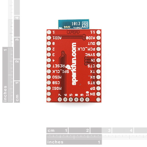
- Interface: USB, UART, and PCM (requires voice CODEC)
- Support for 802.11 co-existence
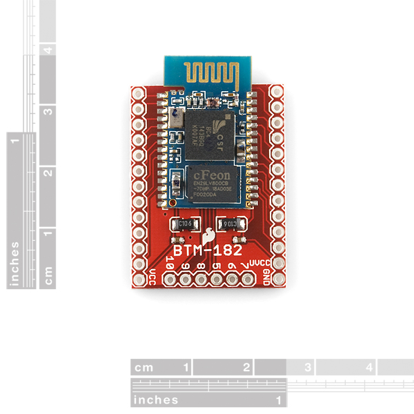
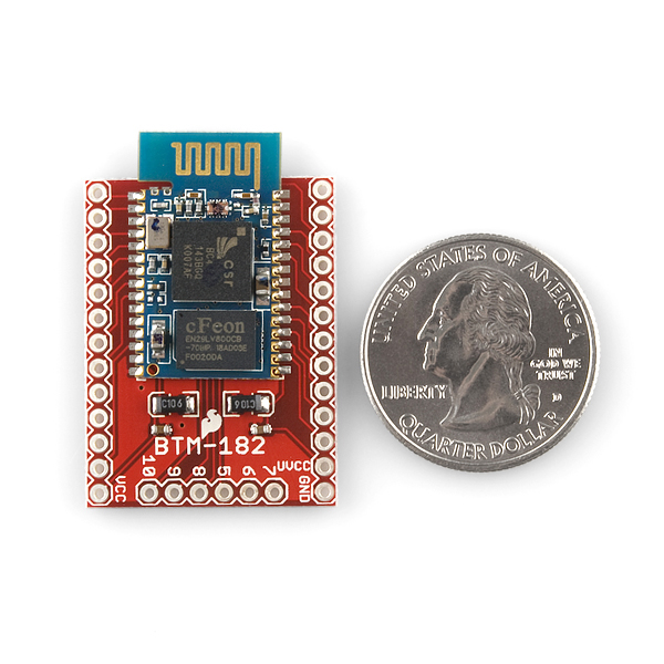
- 25.0 x 14.5 x 2.2 mm
- Schematic
- Eagle Files
- Module Datasheet
- Command Set
- BTM-112 Datasheet for reference only
- Example Design for reference only
Comments
Looking for answers to technical questions?
We welcome your comments and suggestions below. However, if you are looking for solutions to technical questions please see our Technical Assistance page.
Customer Reviews
No reviews yet.
Do you happen to have the breakout available without the module? As i already have the module.
Been meaning to make my own
Could just embed it into your own PCB using the footprint available in the Eagle library easily enough if a blank board doesn't come around.
This all worked effectively and I have likewise possessed the capacity to switch effortlessly between baud rates utilizing. http://ukdissertationpros.com/
How to enable deep sleep or other power saving modes? Can't see anything about it in the AT commands...
Thanks,
Alex
Hi everyone, I hope someone can help me...
I have a pair of these chips setting one as master, the other as slave, and set them up so they "autoconnect" to each other (only each other). This all worked successfully and I have also been able to switch easily between baud rates using the ATL command as shown in the datasheet. However it says it is a fully qualified "Bluetooth V2.0+EDR (Enhanced Data Rate) 3Mbps modulation" which I think means in practice it can go up to a bit more than 2Mbps. My question is how to activate this EDR?? (as it seems to be an option that we need to activate) The datasheet shows a max of 921600 baud with ATL8.
Thanks for any help
Here's a Tutorial I found about interfacing to Arduino with UART.
I figured out a fix, which I will share with posterity. I programmed a microcontroller to spit out "ATL2\r\n" as RS-232 at different baud rates using NOPs to get the bit times right, and fed it to the bluetooth module, watching its response on a logic analyzer, until I could see it talking at 19.2kbaud. Eventually I settled on 115.2kbaud because I want a higher data rate, but one reachable by any terminal I'm likely to use.
So I did stupid and programmed the serial port to a baud rate that I can't match with any device I have around here. I see SPI is another option for communicating with the thing, does that also take the same AT command set? Then I can use that to set back the baud rate. Or maybe just use SPI for everything and forget the UART entirely. Better docs would be welcome.
Anyone have any tutorials for this one? I've tried both SPI and Tx/RX serial to communicate with MATLAB and no results from either. My computer recognizes the device when I connect, giving 2 possible COM ports (6,7) for serial. When I try to use the same MATLAB code which works wired communication (TX/RX) I get no love. I have two 3.3V powers connected (UVCC and VCC) and 1 ground (GND). For TX/RX I have the TX/RX from Arduino connected to TX/RX on the BT. Any help would be most appreciated!
What Matlab functions are you using to talk to the bluetooth module? I've ordered the module and as soon as I receive it I plan on using it with Matlab. We may be able to compare notes. I will being using the bluetooth module with a msp430.
--Robert
I would like to use this device in slave mode to control some I/O. Over bluetooth, how does one control the PIO outputs? Does this require custom firmware? Are there other bluetooth devices that can be use to easily toggle outputs?
Command set doc says that there is 921600 mode (ATL8), but it doesn't work - seems not for this device :(
Seriously nothing? The documentation for this module is pretty much non-existent. Yes, pinouts are great, but what else is there?
Can anyone advise me or point me to a resource for learning how to connect this to an Arduino Pro (3.3V)? I've been looking everywhere but I can't seem to find anything straightforward. All I'm really interested in is what to connect to the Arduino. This board has ~30 pins or so and I know I don't need all of them.
I'm starting with the assumption that all I really need is power and the 4-5 SPI pins. This board is 3.3V or 1.8V, but how do I select this? Is it OK to connect 3.3V to the board is it possible that it may be in 1.8V mode and I will damage something? Or is this selection made automatically?
I also am unsure what the protocol is for sending AT commands. Is this also done via SPI?
Last thing...I see that there are many user programmable pins, but what can these pins be used for?
Thanks for any advice! I bought this board because it is low-cost, tiny, and perfect for a prototype (perhaps future production) but documentation is sparse...
Hi
Something strange is happen with the TX HIGH voltage level in my module. The VCC is 3v and the high on the module TX gets 1.6v. This value is not recognized as an HIGH by MSP430 running at 3v. When using a MAX3222 it works on a terminal section because the MAX converters do a good job. After recognizing that I feed the signal again to another pair of MAX3222 ports and send to MSP. This use of MAX as a voltage converter works. But did you use the BTM182 1.8v version, or I miss something?
Regards,
André
Yeah, I had the same problem with my BTM-182. Apparently the BC04 UART_TX is not really push-pull; it's some kind of open collector/tri-state driver with a weak pullup: http://www.oemblue.com/download/BC04Class1Module.pdf
1.5V is really marginal for Vih on a 3.3V micro, let alone a 5V micro. But since its not a push/pull driver in the BTM, you just need to add an external ~1K pullup to 3.3V, or if you are cheap/lazy, enable on the internal pullup inside your micro.
The internal pullup in my 5V ATmega48 brought the pin to about 3.8V, which is a solid logic '1', and now it's working for me.
3.8V is technically 0.2V above spec for the BTM-182, but I doubt it will harm it as there's virtually no current flowing.
In the MCU->BTM direction I am using a resistor divider to drop the level (390 / 680 ohm for 5.0 -> 3.3V).
Does anybody have any straight forward directions/tutorial/or anything else on connecting this up to an Arduino UNO? I'm new to all of this and I can't find anything telling me how to hook this up, in layman's terms. Any help would be much appreciated!
got that nifty part - played around - success!! works like a charm...
but does anyone have an idea how to put that thingie into the advertised deep-sleep-mode?
regards,
markus
How would you solder this on the breakout board?
The breakout board includes the module and they are soldered together.
I would also like to get the board without the module. I already have a couple of these modules.
Hi,
did you by any chance manage to get SPI of this module to work? I've been trying unsuccessfully so far. Any information would be helpful.
Thanks
$26 markup for a little board with a couple of caps. :S The board costs more than the bluetooth module itself...
boards like this with odd spacing do take a lot of time to design.
Regardless of the price of the module, this is not a unreasonable price for a breakout board like this.
Particularly considering that will probably be a low volume item.
That being said, I would like to pay less for it if I could.
Finally! I am SO getting this!