- Home
- Product Categories
- Components
- ADNS2620 - Optical Mouse Sensor IC

ADNS2620 - Optical Mouse Sensor IC
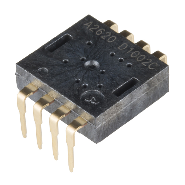
The ADNS2620 is an easy to use entry level, small form factor optical mouse sensor. This little guy is used to implement a non-mechanical tracking engine for computer mice this allows for more compact and cost-effective optical mouse designs. The ADNS2620 is based on optical navigation technology, which measures changes in position by optically acquiring sequential surface images (frames) and mathematically determining the direction and magnitude of movement.
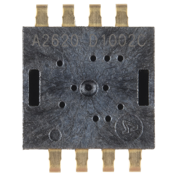
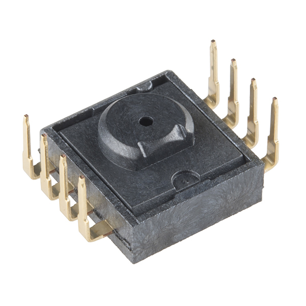
This optical mouse sensor is housed in an 8-pin staggered DIP format and has a resolution of 400 counts per inch with rates of motion up to 12" per second.
- No Mechanical Moving Parts
- Complete 2D Motion Sensor
- Programmable Frame Speed up to 3000fps
- Accurate Motion up to 12ips
- 400cpi Resolution
- Recommended Voltage: 5V
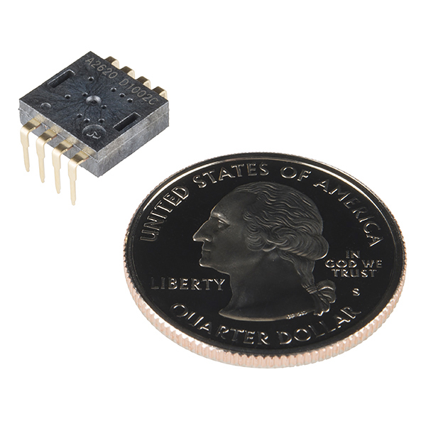
- 12.5mm x 10mm
ADNS2620 - Optical Mouse Sensor IC Product Help and Resources
Core Skill: Soldering
This skill defines how difficult the soldering is on a particular product. It might be a couple simple solder joints, or require special reflow tools.
Skill Level: Noob - Some basic soldering is required, but it is limited to a just a few pins, basic through-hole soldering, and couple (if any) polarized components. A basic soldering iron is all you should need.
See all skill levels
Core Skill: Electrical Prototyping
If it requires power, you need to know how much, what all the pins do, and how to hook it up. You may need to reference datasheets, schematics, and know the ins and outs of electronics.
Skill Level: Competent - You will be required to reference a datasheet or schematic to know how to use a component. Your knowledge of a datasheet will only require basic features like power requirements, pinouts, or communications type. Also, you may need a power supply that?s greater than 12V or more than 1A worth of current.
See all skill levels
Comments
Looking for answers to technical questions?
We welcome your comments and suggestions below. However, if you are looking for solutions to technical questions please see our Technical Assistance page.
Customer Reviews
No reviews yet.
Howdy all! Ant scientist working in a jungle in Panama here! I bought a bunch of these right before I came down to panama (haven't even opened them yet, still getting lab setup). I was hoping they could solve an ant-traffic monitoring problem I will be working on for the next few months. I basically need a really cheap device that I can point at part of a tree, and have it tell me whether or not an ant is walking by. Here's a bigger description of the problem (with pictures!) http://andy.dorkfort.com/andy/digitalnatural/2014/05/30/intro-to-arboreal-ant-sensor-main-project-summer-2014/ (Main Pic http://andy.dorkfort.com/andy/digitalnatural/wp-content/uploads/sites/2/2014/05/img_5388c64dc9c86.png)
I have a couple different ways I was going to attack this problem, but having a basic optical flow detector (that's super cheap) could really be helpful!
This all might not be as easy, or feasible as I think I understand though. As Razorboy notes, I might need to "source a resonator, an LED of the correct color/intensity, and a focusing lens." Hope not! but will see what I can do! So i wasjust seeing if there are some things i should be aware of before I start attacking this problem with this tool!
I hope they continue with this part. It looks very versatile. It should be able to work as sensor for an optical track positioning system. Different lenses should allow it to track motion at a distance. The 18 by 18 pixel matrix is great ( plus 64 levels of gray-scale ). This sensor could be used for a lot of things. I will start a post that collects nifty mouse sensor hacks. Let me know if you are aware of any. http://arts-tech-creation.blogspot.com/2014/05/hack-mouse.html
I do not know what the shutter feature does. Perhaps someone can explain ? Gus in Denver aka 99guspuppet
Oh, man! I have a collection of dozens of these hacks! Plus I've been buying up a bunch of old optical mice and documenting their innards. I'll post some links on your page.
My best find so far (that I found last night, actually) - some people are using an ADNS-3080 to measure movement on model airplanes. That chips has it all: 30x30 sensor, up to 6400 'fps', full 4-wire SPI interface, doesn't need a resonator, Python scripts exist to grab and display the visual data). Their break-out board comes with a long-focus lens (but no LED). Perfect!
http://store.3drobotics.com/products/optical-flow-sensor (These guys haven't had it in a while, but if you search for 'ADNS-3080' on eBay, there are dozens of Chinese knock-offs for ~$20-30).
The ADNS-2620 is fine if you don't need all of that firepower, but, yeah, you're going to need to source a resonator, an LED of the correct color/intensity, and a focusing lens. (I've got bunches of these just from going to Goodwill and buying up $2-3 optical mice. I have a whole (filthy) collection!)
My take on the datasheet explanation is that the shutter feature modulates current (or PWM?) to the LED driver in order to scale illumination to keep the pixels somewhere centered between the highest and lowest values. This would ensure the greatest amount of usable image regardless of whether the mouse were on a bright white surface or a black surface.
... and so if your goal is to hack this for tracking motion at a distance, you would first want to provide optics to focus the image on a plane in front of the sensor (having the ability to do frame dumps would be very handing in setting up the optics).
Once you have the optics how you want them, you could emulate the shutter feature by mounting a circular grayscale smoke filter ahead of the optics on a stepper motor or servo, then use the LED output signal to rotate the filter accordingly.
... or for a more elegant filter solution you could mount two polarized filters, one fixed and one rotating. The filters would span from near transparent when aligned to opaque when at right angles.
Will there be a complete kit with the HDNS-2100 Lens, HLMP-ED80-xx000, and the HDNS-2200 LED Clip available?
Agreed! Been wanting a kit ever since they dropped the last one... Just missed out on it.
Does it need the datasheet referenced clip, lens and LED?
Reading the datasheet, it almost certainly does for any kind of reasonable performance. They're likely not integrated so that an OEM could design a more space-efficient/different alignment system if they desired.
Anyone got a good idea how to make my own lens for this small little thing? a lens that could get rough focus about 10-20cm away?
So after lots of messing around, i got the first steps to it working going on! Based off this: http://tim.cexx.org/?p=613
I modded an arduino sketch and a processing sketch to read the image, and display the image in processing: https://github.com/quitmeyer/AntSensorPrototype/tree/master/OpticalMouse%20Sensing
Go into the examples folder and look for ADNScamera for the arduino, and the readmouseimage sketch for the corresponding one.
Things are STILL way hacky. The guy from http://tim.cexx.org/?p=613 has a nice pinlayout and schematic, but I didn't have an oscillator, so I just put at jumper wire between the osc in and out. I'm sure this is bad, but it actually functions and responds! I also don't have a lens for it.
Still not quite there but here's this: http://home.roadrunner.com/~maccody/robotics/croms-1/croms-1.html
Have you had any luck coming up with some alternate optics for the IC? The only other consumer lens I can think of that would be small enough would be a laser pointer lens, but people seem to be using those for macro photography, which I don't think will do you much good.
For more information you might take a look at the schematics and code on our retired optical mouse board: https://www.sparkfun.com/products/retired/10026.
I've seen papers of these sensors being used for so much more. It placed one on each wing and used it to fly between two buildings (they used different lenses if I remember correctly). They measure pixel change, so parallax can do amazing things if you think outside the box. Mice put it at a fixed distance and use it to measure motion. The opposite could be true. With a given motion you could get an idea of distance. I've never seen an accuracy for this method, so it might be terrible.
At one time I wanted to place these on the bottom of a quadracopter to get an idea of motion and/or distance to ground. I also thought about placing one facing out and spinning it to see distance to nearby objects (gyro to get rate of spin allows you to get distance). All theoretical and in my head but I thought I would share in case it sparks ingenuity in someone else.
So I assume the interface one this chip is basically 3-wire bi-directional SPI, but minus the Slave-Select pin? Has anyone had any luck hooking a chip with this interface up to a SPI bus with multiple slaves? Or do I need to implement a SPI master for each chip I want to use? (what a waste of uC resources!)
I tried working with a similar chip a few years ago to make an underwater mouse and I found that without the specialized lens getting the optical alignment right was very difficult.
With the pin offset I'm guessing this isn't breadboard friendly. Is a breakout board in the near future if this is the case?