- Home
- Product Categories
- PTH ICs
- H-Bridge Motor Driver 1A

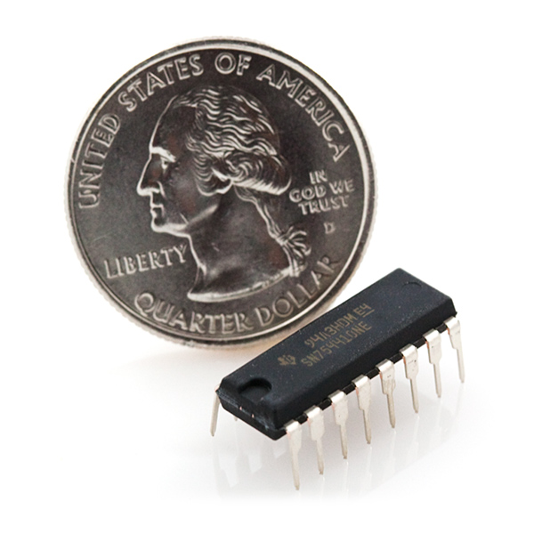
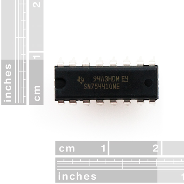
Faster, cheaper, smaller, better, right? The SN754410 Quad Half H-Bridge is just that. Capable of driving high voltage motors using TTL 5V logic levels, the SN754410 can drive 4.5V up to 36V at 1A continuous output current! Please see datasheet for more information. This is a pin to pin compatible replacement for the L293D.
**Datasheets: **SN754410
H-Bridge Motor Driver 1A Product Help and Resources
1 of 1 found this helpful:
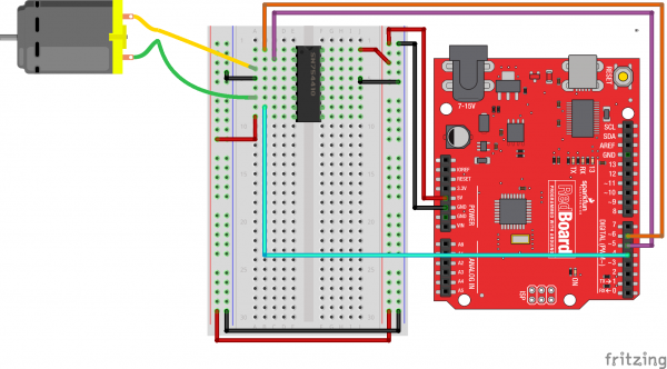
Arduino Example
For an example of using the H-Bridge motor driver, try checking out experiment 9 that is used in the SparkFun Tinker Kit:
Core Skill: Soldering
This skill defines how difficult the soldering is on a particular product. It might be a couple simple solder joints, or require special reflow tools.
Skill Level: Rookie - The number of pins increases, and you will have to determine polarity of components and some of the components might be a bit trickier or close together. You might need solder wick or flux.
See all skill levels
Core Skill: Robotics
This skill concerns mechanical and robotics knowledge. You may need to know how mechanical parts interact, how motors work, or how to use motor drivers and controllers.
Skill Level: Rookie - You will be required to know some basics about motors, basic motor drivers and how simple robotic motion can be accomplished.
See all skill levels
Core Skill: Programming
If a board needs code or communicates somehow, you're going to need to know how to program or interface with it. The programming skill is all about communication and code.
Skill Level: Rookie - You will need a better fundamental understand of what code is, and how it works. You will be using beginner-level software and development tools like Arduino. You will be dealing directly with code, but numerous examples and libraries are available. Sensors or shields will communicate with serial or TTL.
See all skill levels
Core Skill: Electrical Prototyping
If it requires power, you need to know how much, what all the pins do, and how to hook it up. You may need to reference datasheets, schematics, and know the ins and outs of electronics.
Skill Level: Competent - You will be required to reference a datasheet or schematic to know how to use a component. Your knowledge of a datasheet will only require basic features like power requirements, pinouts, or communications type. Also, you may need a power supply that?s greater than 12V or more than 1A worth of current.
See all skill levels
Comments
Looking for answers to technical questions?
We welcome your comments and suggestions below. However, if you are looking for solutions to technical questions please see our Technical Assistance page.
Customer Reviews
5 out of 5
Based on 1 ratings:
2 of 2 found this helpful:
These little guys work great!
A perfect solution for driving small motors. Works great for robotics applications. I would recommend these motor drivers!
-------------------- Tech Support Tips/Troubleshooting/Common Issues --------------------
Driving a Stepper Motor
Try looking at this tutorial for driving the Stepper Motor with Cable => http://www.hobbytronics.co.uk/stepper-motor-sn754410 .
Here is a really nice tutorial on using one of these. They were nice enough to link here so I thought I would link them back.
http://itp.nyu.edu/physcomp/Labs/DCMotorControl
Looks like you can PWM the enable pin for speed control?
thank you very much for the link!
thanks for the link! it helped me out a lot!
This is a great chip. I just hooked it up to my Arduino and am using it to drive a tank tread base.
Found an excellent video tutorial on driving DC motors using a microcontroller. Parts 1-3 provide an overview of what an H Bridge driver circuit is. Part 4 shows how to connect the SN754410 chip to the logic lines on your controller, which line to do PWM on, etc.
The data sheet you really want (for DC motor control) is found on the TI web site, but search for the L293 and grab that data sheet. Have a look at Figure 5 on Page 9 to see how to use the 754410 as a reversing controller - you can just ignore the anti-kick back resistors. Vcc2 is also handled in the 754410. The usual 7400 or 7404 (or similar) can be used to invert a single control signal, or a microcomputer (like ATTiny) can provide the inputs.
i had a look at the diagram on page 5 .. and it looks like the protection diodes (as labeled on the diagram ) aren't even functional ?
for example the diode off of the ground ( the one immediately to the right of the motor ) flows AWAY from the ground ...
can someone confirm that this is a bit wonky ?
im thinking i might get a few of these to run some steppers but im kind of at a loss right now :D
As the current going through an inductive load (such as a motor) stops and starts, it induces large voltages, or at least, has the ability to.
The diodes are facing the correct way, they are there so that any large voltages above your power rail or below your ground rail flow into said rails, preventing your motor driver from ever seeing these voltages.
Think about it, if the diode flows into ground, the majority of your current would get shorted through the diode, which is lower resistance than your motor.
Hello. I would appreciate if you help me. Can I use 1N4148 or 1N4004 as rectifier diodes for DC motor.
I used 1N4001
this may seem like a silly question, but when using this chip for dual direction motor control, how could you even add in the diodes? i don't really see a way to do this at all since the current will have to flow both directions and the protection for the one way would essentially short the current when the motor is driven the other way.
Good question, I had to research it bc I want to do just that. Here is what I found
Wouldn't the inductive kick cause harm to the chip? The motor only kicks back on startup or shutdown, so if you don't plan to be starting and stopping the motor too much (i.e. continuously running it) I don't really see it as too much of a problem, but it still exists...
This chip is pin compatible, but not functionally equivalent to the L293D. The L293D has internal flyback diodes, which catch what would otherwise be high voltage inductive noise (sometimes even in the kilovolts). With the SN754410, you must use external flyback diodes in your H-Bridge.
Even though you might feel like you can get away with it, it's a VERY bad idea to use this chip without a flyback diode. It's not just the driver you have to worry about, it's your entire circuit (MCU, accelerometers, expensive XBee, etc.). Eventually, your luck will run out, even if you don't turn it on and off frequently.
You can use a bridge rectifier as the protection diodes for the device if you want. The AC leads go to the chip outputs, the pos lead goes to + and the neg lead goes to gnd. I think this part DOES have internal protection but being paranoid and having enough 1N4007 diodes in the junk box to choke a moose (I was given over a lb of them with cut leads!), I wired up some external protection anyway.
I'm confused, the datasheet says the flyback diodes are there on page 2. Is this the wrong datasheet?
I saw that, too. Is superbrad right, or are there flyback diodes inside?
In addition to showing internal diodes on the equivalent output diagram, the datasheet for this chip [i]also[/i] lists clamp voltages of -1.1v and Vcc2+1.4v for kickback currents of 500 mA and clamp voltages of -1.3v and Vcc+1.9v for kickback currents of 1A.
The L293/L293D data sheet shows clamp voltages of -1.3v and Vcc+1.3v for 600 mA kickback currents for the L293D, and none for the L293.
The "TI tech support answer" Limor Fried got was "I never trust internal kickback diodes", which doesn't say anything one way for the other.
Do you mean anti kickback diodes? I see no resistors on page 9, fig. 5.
Is there a package in the Spark Fun Eagle library for this part?
https://github.com/alexwhittemore/AlexW-Eagle-Libraries
I guess not.
This is a good IC for robotics. It is a quadruple half-H driver but by connecting certain pins it can be used as a dual full H-bridge. See data sheet for more info.
This chip sounds good but my power supply is 3.7v. Can someone point me to a H-Bridge here that supports lower voltage?
Sorry for the late reply, The Toshiba TB6612FNG is a good choice for lower logic and motor voltages. The datasheet specifies that the motor voltage should be 4.5V to 15V, but I've used it on Lipo-powered projects without issues.
I got this chip fairly recently and I decided on writing a blog tutorial describing how I set it up.
I just bought two of these and they are not working - I followed the tutorial John linked, but regardless of the input to "1A" and "2A", "1Y" and "2Y" never go high.
Edit - nevermind. Forgot to provide power to the controller.
I've got this chip to work by following this tutorial and using the information regarding 'flyback' diodes from this tutorial. The data sheet also has an important schematic on page six (fig.3) describing the proper orientation for the diodes which I used in my circuit. It matches the orientation described in the latter mentioned tutorial.
Is there a difference between giving LOW to Pin 1, which disables the motor, and giving LOW to both Pin 2 and 7, which also stops the motor? Would it be okay for me to just tie Pin 1 to Pin 16 +5v and just give LOW to both logic pins in my program when my motor is off?
Dose the coin include in package? ;)
Do they have these with 3v logic level?
So I need to power a solenoid to fire using a positive voltage. Which one 1Y or 2Y should I connect to the positive terminal of the solenoid to have it fire correctly?
SFE sent me one that didn't work. I emailed customer service and they won't respond. Why?
Does anybody know if I Can put a Darlington NPN transistor in each output to control more current? I need to control this stepper... https://www.sparkfun.com/products/9238 and I need at least 4 amp, so I was wondering If I may adapt this to the motor using darlingtons I will use Arduino. Help Me please!
Is there a heat sink for this?
No, Tozian, there isn't a heat sink.
I hooked one of these up and found that it took an enormous amount of current to drive a small load (>5V at 1A from a bench top power supply on VCC2 to drive an LED) Am I doing something wrong or is this just what you get? I need to drive two hobby motors off of this thing and I'm beginning to doubt I can do this with 4 AA batteries.
Never mind, found the problem. I had forgotten to connect to Ground.
Is it possible to connect 2 of them to 1 Arduino uno?
Hi, I m doing a project on controlling two 15kw bldc motor using fpga via H-bridge, Anybody has any idea abt that. What type h-bridge I need to use. Motor specifications are 250-350 VDC,
As a note to anyone considering using this with anything other than 5V steppers/DC motors. These things can get VERY hot, and I would recommend using a heat sink or small computer fan.
Hey guys, I am using two of these in parallel to with an Arduino pro mini (5v) to drive the Tamiya Twin Motor Gearbox. My battery is a 9v, so I need to limit my voltage supply to 3v for the motors. When I set my PWM output to 80 (about 1/3 of 255), I measure around 7 volts on my multimeter (no motor connected). My question is: why isn't the voltage around 3v when PWM is at 80? In other words, does the PWM from the Arduino linearly control the output to the motor? Do I read 7v on the multimeter because there is no load on the chip? I connected a resistor between the outputs and the readings were around 2.5v. I've used this chip before without issues, but I'm not sure what's going on here. Any help is appreciated. Thanks!
Never mind... I found a short in my wiring.
Okay, Gonna make myself look stoooopid here, I'm sure. Just got the H-bridge today, eagerly popped it into a breadboard to check it out. I built the most basic of circuits: 1,2EN are run to the +5V rail; Vcc1 (pin 16) goes to +5V rail; Vcc2 (pin 8) gets +3V. Pins 4,5,12,13 all go to Gnd. 1Y and 2Y run to the motor. According to the Data Sheet, if I send 1A or 2A high, the motor should turn (direction determined by which is taken high). Right????? Here's where I got lost....I ran 1A and 2A to momentary switches then onto the +5V rail. Powered the circuit up, pressed the 1A switch and got NOTHING. Pressed the 2A switch and got NOTHING. But wait, there's more... while fiddling, I ran the switch (from 1A) to Gnd, and viola, the motor began turning. So I ran the switch from 2A to the Gnd rail as well, and shock of all shocks... the motor turns one way when the 1A button is pressed, and the other way when the 2A button is pressed.... WTF??????? Any thoughts on what I've done here. I've managed the impossible, but I have no idea why!!
Thank you for the link. It is very helpful and straight forward directions.
I'm very new to programming and the Arduino, but I have a question regarding this. After programming this IC, do you still need to use the arduino? Does it still have to be connected or could you disconnect it and run it on its own with the programming installed. Is this the same with anything you do with the Arduino?
Thank you!
You will still need to properly wire up the IC into your circuit. The Arduino board takes care of voltage regulation, USB to serial conversion, that type of thing. You can still definitely use the IC without the board, but keep in mind you will need to incorporate additional components if you want to have access to those features still.
Wonderful! What if I wanted to use the arduino pro mini to control two dc motors... If I used the Arduino board to program the mini, I no longer would need the Arduino board and just use the mini without additional components correct? Or not?
Thank you so much for your help by the way!
If you want to program a Pro Mini, you would want to use an FTDI basic 5v or 3.3v depending on the version of the Pro Mini. However, you are correct that once you have the Pro Mini programmed, you can remove the FTDI and run the mini by itself.
Wonderful! Thank you!
Does anyone have idea of IC which would do just the opposite of this one? To clarify I need IC which would have 4 inputs of variable voltage (3 - 24V) and 4 outputs of stabilized voltage of 5V. Hope you understand what I'm looking for.
When I used Arduino to control the motor, this works perfect, but when I used Teensy to control the motor, the motor was vibrating a lot, and the speed is slow, anyone knows why that happened? Thanks.
Hi, i was wondering what pin should i put a flyback diode on? I am a newbie to robotics. so...
The outputs, 1Y,2Y,3Y,4Y. See datasheet pg 6 for diode connection example. Also see http://www.robotroom.com/HBridge.html sections on D1 & D3, D2 & D4 for a great explanation of what's going on.
Can this be used with pwm?
I've used this chip with PWM on the enable pins, seems to work great.
Another nice tutorial of the logic of this chip, Pg 30 and a few after.
Hey guys!
I'm using this to drive two small gear motors with an Arduino. I'm have trouble disabling the motor using the enable lines. I can completely disconnect the Enable line and the motor continues running.... bringing enable low does nothing....
Please help!
Edit: sorry solved the problem. It was a programming error....:(
I'm using one of these chips to drive two motors in a little project.
The data sheet shows that pins 4, 5, 12, 13 are all gnd (and heat sink).
If I am not really worried about the heat, do I still have to wire all of these pins? Or can I assume they are internally connected and I just have to connect one to ground?
Thanks!
just bought 2 of these. I tested one of them on the breadboard by following john4's link http://itp.nyu.edu/physcomp/Labs/DCMotorControl and it worked great. after that I took my second chip and soldered it onto a proto board, but it only goes forward regardless if the signal sent to the A pins are high and low or low and high. I doubled checked everything and I THINK I connected everything correctly. could this be a bad chip?
edit just found out what was wrong. I used an adruino pro mini for my project and when I did a test on my circuit the arduino tilted in a wierd angle so not all the pins were touching. anywho after I soldered down the arduino and everything is working.
The IC works great. However all of the four that I just bought have been a pain in the butt since they keep on jumping out of my breadboard (just enough out so that some connections are severed).
Hi I am new to the Arduino, but I have been into robotics and electronics for some time. I am looking for an IC that will convert PWM signals into analog +V, or -V. I don't want just full power forwards, or full power backwards. Can I get what I want with this IC, or if not, what would you recommend?
I found out myself. Never mind. Works great except that the ones that I ordered pop out of my breadboard all the time :(.
hello Member200027, you can download a library designed with the footprint for this driver at(in the end):
http://www.electro-tech-online.com/electronic-projects-design-ideas-reviews/39867-sn754410.html
Open the zip and just copy HBridge.lbr in to your eagle libraries folder. Then select it in eagle so you can add that component to your project.
good luck!
Is there an Eagle file for this?
This is a very nice chip, However they should offer a heat sink for it because it gets hot. I am using it for some tank tracks and interfacing it with an Arduino. The infrared sensor that I bought off this site works very well for my application.
okey hahah i forgot the tutorial... here it is:
http://www.kronosrobotics.com/an101/AAN101.shtml
Take a look at this! at the end of this tutorial it shows that you can attach two of this in parallel,it is to stack two of them, so you can obtain double power foy your motors!
I haven´t try this yet, but i´ve two of this IC and tomorrow i´ll se how it works....
the only problem is to extract the heat...
any idea about this?
Can anyone tell me where to put flyback diodes on this chip? I've read a hundred times that I need them, but I can't find any clear description of where to hook them up. (I even got a Masters in electrical engineering student to help, and he didn't know, either...)
Thanks!
The description of the chip says you can put 1A through each side of the chip. I have a motor that needs 1.25 or 1.5A. Can I just connect power, ground, signal, etc for the one motor to both sides of the chip to "split up the burden"? Or will I probably still end up blowing it up?
How do I use this with the Dual Motor Gearbox? I got my ATTiny, I just need to be able to drive the motors.
Never mind, I'm gonna use an NPN power transistor :^D.
Now I'm thinking that perhaps I will build a little roller-ball mouse robot too :) and each motor is going to need to turn the roller ball in both directions. Sooo... how the heck do I use this?
Where is the breakout board for this?
And it needs mounting holes
Is there a way to use one of these and have a motor go forward, reverse, or coast? Most of the examples I have seen on the web only do forward, reverse, and brake. I need coast, not brake.
Yes. Disable the enable pin, and you'll get coasting.
Is it possible to drive a nxt motor whit this chip?
So I ordered 2 of these a few days ago, and I got 2 chips with 4 rows of pins each. Um?
I think they might be the http://search.digikey.com/scripts/DkSearch/dksus.dll?Detail&name=497-4280-5-ND, is it? The code on them is i believe 063EC and perhaps K15039. Can anyone help?
Thanks in advance,
Ashvin
Could you use two of these to drive a stepper motor?
Yes, as GuShH points out these will drive stepper motors (I've done so several times). It just takes one chip to drive a bipolar stepper (I've used these to drive the steppers SF used to carry).
You just need to send the right high and low signals to the chip (and in the correct order).
These are not made for stepper motors. Use a stepper motor driver instead:
http://www.sparkfun.com/commerce/product_info.php?products_id=9402
I beg to differ, you need to use h-bridges to drive bipolar steppers.
However this is just the output stage, you'd still need to generate and send the correct pulse sequences -- This is where a stepper controller kicks in, but you can mimic one with almost any MCU.
While this chip WILL drive stepper motors when used with a MCU and some software it WON'T do micro steps, you'd need an analog driver with a DAC in the output for that. But in most cases you don't need micro stepping, especially if you have some kind of gearing in the drive train.
I am interested in making something with some tiny stepper motors (taken from 3.5" floppy drives), although I have to admit that I don't know a whole lot about motors yet. What would prevent this chip from being used to drive a small stepper? Is there something about stepper motors in general or does the size of the motor matter?
Awesome chip! Just got a few from a friend that has bin holding my hand through the dark with this stuff. Robot here I come!
I need a friend that knows about this stuff. All my friends act like I am speaking Chinese when I mention anything about microcontrollers or robotics. lol.
Love using these things in my robots except I fried one and soldered the other one and get get it off (all my fault : /) these are wonderful and will be getting more.
how can I control the speed of a dc motor using an arduino?
I got one of these to use in a picaxe 18 high power board (CHI035). It does not work as well as an L293D.
I used the CHI035 to replace an 08 based picaxe motor controller which includes an L293D. That controller was used with a Tamiya tracked chassis and it worked fine.
Once I placed the CHI035 (with this chip installed) on the track chassis, this chip would quickly heat up and the voltage would start to drop. With in a few seconds of operation it would drop below 0.5V.
I replaced this chip with a REAL L293D and it works perfectly.
I feel dumb now but I answered my own question.It can be used to control two motors independently forward and back by keeping 1,2EN and 3,4EN HIGH at all times and changing the A inputs.
In dual full H-bridge mode, mentioned in the post below, could it be used to independently power two motors forward and backward? Or would I still need one per motor? And if so, how do I do this? I can't figure it out via the schematic.