
Beginning Embedded Electronics - 5
Lecture 5 - AVR GCC Compiling
Sorry for the confusion. When these tutorials were written and photographed, we used the ATmega8. We now carry the newer ATmega168. You will find all ATmega168 information in the following pages, but the pictures will show an ATmega8.
I know very little about the ins and outs of the AVR-GCC compiler. I've learned a few basics that helped me along the way, but when you run up against a jam, google and AVRfreaks.net are your friend.
First, we did the blinky. Open this code in PN2 and make sure you can compile it. Click on Tools->Make All. The window in the bottom screen should say 'Process Exit Code: 0' meaning the compilation was successful. If not, there should be a line number listing of the problem line of code. Be sure to check above and below the indicated line for problems.
In the second example C file called basic-out-atmega168.c (basic-out.c for the ATmega8), I've inserted a handful of functions and lines of code. First of the black magic:
#define FOSC 16000000
#define BAUD 9600
#define MYUBRR FOSC/16/BAUD-1
What is all this noise at the top of the file? This is a series of defines that calculates the MYUBRR variable with the correct number. Since serial communication depends on the fact that we will be transmitting and receiving at 9600 bits per second, it's crucial to tell the ATmega168 what bit rate to set. Because the ATmega168 is dictated by the oscillator that it is using, we must correctly calculate what value we need to load into the ATmega168 hardware so that the ATmega168 sends the serial pulses at the correct rate with a given oscillator type. In our case, we are using a 16MHz oscillator so we can setup the define statement as shown. MYUBRR is calculated at compile time and is loaded successfully into the hardware UART during run time.
A reader's untested submission:
The UBRR value calculation in Lecture 5 could be more accurate with the following macro:
#define MYUBRR (((((FOSC * 10) / (16L * BAUD)) + 5) / 10) - 1)
There is also pretty useful web form for UBRR calculation:
static FILE mystdout = FDEV_SETUP_STREAM(uart_putchar, NULL, _FDEV_SETUP_WRITE);
This line creates a buffer for the printf statement to post to. I'd rather not explain it, simply because I don't understand it. When I am working on a new coding project I never start from a blank page, I *always* start from a known working program and slowly bring in bits of other projects to get the code I need, writing bits along the way. Please start from this printf example and build away. The purpose here is to get your printing string to the terminal window.
Checkout the ioinit() function. You'll notice some new commands.
U
HTML clipboard CSR0B = (1<<RXEN0)|(1<<TXEN0);
This is the really funky, but very practical, method of setting bits on the AVR series. RXEN0 is defined in some file as '5'.
Finally, we see the very comfortable line of code:
printf("Test it! x = %d", x);
What did you say? This is not a comfortable line of C code for you? Ok - printf is somewhat of a universal function to pass serial strings and variables to the outside world. The line of code above will pass the string "Test it! x =" to the serial port and it should display on the terminal window. After that, the %d gets converted to an actual decimal number so that whatever digital number is currently stored in the variable x gets printed to the terminal screen. So what? This simple printf statement allows you to print variable contents and see what's going on within your C program.
Time to load the basic-out-atmega168.c file onto your breadboard. Open up PN2, compile basic_out-atmega168.c. Power up your board, click on Tools->[WinAVR] Program from within Programmer's Notepad. The code should now be loaded onto your ATmega168. If WinAVR throws a verification error, try again. Open up the terminal window at 9600bps if you don't already have it open.
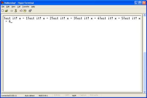
Text output from the ATmega168 and MAX232 circuit
All right! We've got output from the ATmega168! Now let's talk about some more of the code:
sbi(PORTC, STATUS_LED);
Another funky one if you're not used to the AVR series. To toggle a GPIO pin (general purpose input/output pin), you need to read the state of the port, mask the bit change into the state-word, and then write the 8-bits back onto the port effectively modifying just the one bit. Instead of doing all that by every time you want to toggle a port pin, there's this handy macro:
#define sbi(var, mask) ((var) |= (uint8_t)(1 << mask))
SBI sets a bit. CBI clears a bit. You have to specify which port you're working with and which pin you want to alter. Throw another define at the top of your code:
#define STATUS_LED 0
Now you can control your STATUS_LED on PORT C using these two simple commands:
sbi(PORTC, STATUS_LED);
To turn on the LED and
cbi(PORTC, STATUS_LED);
To turn it off.
You should have an LED tied to pin 23 on the ATmega168. When in doubt, toggle your status LED to figure out where the code is hanging or use a printf statement.
There are also some tweaks to the delay_ms() routine. Because we increased the oscillator from 1MHz to 16MHz, I increased the loop iterations to tie up the processor for longer. I didn't do any real calculations so don't depend on my delay_ms routine. delay_ms(1000) looks to be roughly a 1 second delay.
Open basic-in-atmega168.c (basic-in.c for the ATmega8) and load up your breadboard:
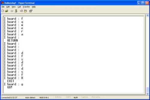
Key presses and various responses
Here we see that whatever character we hit, the ATmega168 responds with 'I heard : ' and the character. Also, if you hit return, X, or g, you will see various special output.
key_press = uart_getchar();
printf("I heard : %c\n", key_press);
if(key_press == 'g') printf(" GO!\n");
if(key_press == 'X') printf(" EXIT\n");
if(key_press == 13) printf(" RETURN\n");
uart_getchar sits waiting for a character to appear in the UART. Once received, the ATmega168 outputs the character (%c) and goes to a new line (\n). It then checks to see if the key press was one of three special cases. If so, it prints an extra string accordingly. I hope you are starting to see the power of the input/act-upon/output that a microcontroller is capable of. With a little bit of work, you could program your own text-based adventure game. Go to town.
Remember back when you were struggling to get your power supply wired up? Nice job! Time to heat up your irons.
We love feedback! Please report typos, comments, or recommendations to spark@sparkfun.com.
Lecture 1 - Background and Power Supply
Lecture 2 - How to Get Code Onto a Microcontroller
Lecture 3 - What is an oscillator?
Lecture 4 - UART and Serial Communication
Lecture 5 - AVR GCC Compiling
Lecture 6 - Soldering Basics
Lecture 7 - SMD Soldering
Lecture 8 - Eagle: Schematics
Lecture 9 - Eagle: PCB Layout
Lecture 10 - Eagle: Creating a new part
Common Mistakes, Tips and Tricks
Adding to what Neil said above, you can also change the FOSC and BAUD settings in the code if you want to use different clock speeds and baud rates with your AVR.
This worked great for me on an ATmega48 at the default 1MHz internal clock using minicom under linux at 2400 bps.
Thanks Blizzrad. I am running my ATMega8 at 1MHz and was getting garbage printed to the terminal. I switched to 2400bps and updated FOSC and BAUD settings. Now it is working great.
These programs would scare the balls off a brass monkey. Go to MIT's example page and study it there -Much easier to understand whats going on http://hlt.media.mit.edu/wiki/pmwiki.php?n=Main.AVRProgrammingAdvanced
I completed this tutorial using the ATMega328p. I had quite a difficult time with this tutorial initially.
At first I thought we were going to program the chip through the serial port using the DB9 connector. After realizing that you have to load the program onto the chip first using the parallel port or your program of choice, well, it works great.
My wife, however, is not impressed.
Now that's the funniest comment.
Do you, or anyone else, have a copy of their makefile that they used in combination with the usbtiny device (rather than the parallel port)?
Would be handy to have these tutorials updated to include the options for using the usbtiny device since I'm sure not many people have a parallel port.
I found this guide from LadyAda extremely helpful when modifying the makefile for using the AVR Dragon. It looks like there are examples with the usbtiny.
Is it normal to take 315 seconds to upload 1826 bytes to the AVR? Thats 46bits/s, seems kinda slow.
I was using a USB-Serial adapter with the serial programmer and that was causing the slowness. Hooked it up to the actual serial port and uploading to the AVR was done in a fraction of the time.
The 16MHz external crystal can at best work for a baud rate up to 19200, it does not work with any higher baud rate for the accuracy is too low after the prescaler division.
To work for higher baud rate such as 115200, a precise UART friendly external crystal frequency is needed, such as 11.0592MHz (115200 * 96) or 7.3728MHz (115200 * 64).
I've not tried these UART friendly crystal oscillators on AVR, because I recently have done a project using ST's STM32F101RB, an ARM Cortex M3 MCU, it's just about US$2, and with more features than similarly priced AVR or other architectures (PIC, C51 etc), and the performance is just not comparable.
ARM Cortex is the king, I'll abandon all other CPU architectures from now on, except in some rare cases where the extreme low power requirement is a must.
I'm still hoping eagerly that someone will help figure out how to get scanf to work (see comments above). I tried this for my senior design project, but never quite figured it out.
Can someone please explain to me if this should work with the RS232 Shifter Board (http://www.sparkfun.com/commerce/product_info.php?products_id=133) in Lesson 6?
If not, why not? What do I need to change and why? Rather than just the steps to get it working, I'm trying to learn the ins and outs.
Thanks for the awesome tutorials. Keep 'em coming!
Don't know where has been mentioned, but somewhere in here it refers to downloading the amtega168 manual. In that manual, on page 195+ are tables that show the UBRRn value and the associated baud rate error for several clock frequencies. So, unless I am misreading this, by setting the internal 8 MHz clock to NOT divide by 8 (lfuse bit 0x7 to 1), the error percentage for 9600 baud drops from ~7 to 0.2. This may alleviate the need for an external crystal.
Okay, so now I've tested it with the internal oscillator set at 8 MHz and the lfuse div8 off and it works fine. I also changed the following:
#define FOSC 8000000
#define MYUBRR 51
in order for everything to be in sync. I was getting an error before I changed the above MYUBRR, in this line:
//USART Baud rate: 9600
UBRR0H = MYUBRR >> 8;
It may not be as accurate as with an external crystal, but the part count is lower. :)
An additional note is required here on the error I was getting. In the original article's formula for MYUBRR, if I placed () around the formula, the error mentioned goes away. Like:
#define MYUBRR (FOSC/16/BAUD-1)
get's rid of this warning around line 65 or so:
//USART Baud rate: 9600
UBRR0H = MYUBRR >> 8;
In function 'ioinit':
warning: suggest parentheses around '-' inside '>>'
Forgot to mention; this works both breadboarded and on my stk500.
And I am using a FT232RL breakout board I got for another project. Makes it very simple to use, just a couple of jumpers: TX, RX, and GND. I don't have any MAX232 chips.
Hay when I try to download the basic-out-atmega168.c file I get a basic-out-atmega168 file without the extension. Then when I open it in PN I just get some strange blabla. When I tried to downlaod that ledblinkfile in the second tutorial I got the same thing. Also there was no makefile at all in that download for me. (I used Google to get those.) How comes? Is it because I'm in Europe? Or am I doing something wrong here?
I had the same problem. Use 7Zip to open it. When you see basic-out-atmega168 double click on that, and then you will see the two files you need (the .c and the Makefile). Unzip those to your folder and you're good to go.
Great tutorial! Just as a note though, the user submitted response can be simplified. When simplified this
(((((FOSC * 10) / (16L * BAUD)) + 5) / 10) - 1)
turns into this
FOSC/16/BAUD-(1/2)
which is only .5 from your original equation.
For what it's worth, the formula for error percentage is:
(( desired baudrate / actual baudrate) - 1) * 100
The actual baudrate is:
FOSC/(16(UBRR+1))
The UBRR value is:
(FOSC/(16desired baudrate))-1
I have found that in C++ sometimes the order of calculations don't work in the standard order (MDAS) as expected, if put in certain data structures. ...or, it could be the operator... :-)
My max232 IC was an ADM232L chip, so after following the connection schematic and testing the IC I was getting garbage.
The solution was that I went back to the ADM232L data sheet and connected the capacitors as suggested. This made the circuit work for me, I hope this helps someone :D
Great tutorial! I am now trying to get scanf to work. However, I seem to be unable to get scanf to wait for user input. My code prompts for user input (via printf), then does scanf. However, when it runs, the terminal spits out my printf statements constantly. I am using AVR Studio 4 and an AVRisp. I wonder if I am initializing stdin incorrectly?
I think I should modify the code in this tutorial by adding:
static FILE mystdin = FDEV_SETUP_STREAM(NULL, uart_getchar, _FDEV_SETUP_WRITE);
and
stdin = &mystdin;
I think I should also have the function uart_getchar from the tutorial's code, and I've included stdio.h and avr/io.h. I think I should then be able to call scanf in my main function, but it doesn't work. Can someone help me?
static int uart_getchar(FILE *stream)
{
while( !(UCSRA & (1<<RXC)) );
return(UDR);
}//uart_getchar
I had forgotten to include my changes to uart_getchar(). My version is posted above.
check your fuse bits, check those stupid capacitors around the crystal. If they're not the right kind the whole thing goes down.
The C file compiles OK but when i tried to program the IC it returns this error :
avrdude -p atmega168 -P lpt1 -c stk200 -U flash:w:basic-out-atmega168.hex
avrdude: AVR device not responding
avrdude: initialization failed, rc=-1
Double check connections and try again, or use -F to override
this check.
avrdude done. Thank you.
make.exe: *** [program] Error 1
I wanted to do this tutorial but did not have the max232 to do the serial but did have an arduino (it has the ft232rl usb to serial chip). I pulled the atmega out of the arduino (I didn't know what the program was on it and did not want to cause conflict) and attached the tx and rx ports to the tx and rx ports on the breadboard atmega168 circuit and it works great! Thanks for the great tutorials they have really helped me get beyond basic arduino programming.
Can anyone tell me what F_CPU = 8000000 means in Makefile? If I want to run my uC at the default 1Mhz and TX/RX at 2400bps, should I change the define to:
define FOSC 1000000
define BAUD 2400
and then also change F_CPU = 1000000 ?
Appreicate any help. I am new to this.
Does anyone know of a tutorial or book that will take me through the AVR-GCC programming language? I have been programming for years and I keep hitting walls.
I appreciate your time
The Trusted One
AVR-GCC is the name of the compiler, not the language. You write code in C or C++ and then compile it using the AVR-GCC compiler. If you've been programming for years, then I assume that you are already familiar with C or C++ or can easily learn them. You probably need to learn more about the hardware-specific features of your microcontroller, since the code for accessing these hardware features is non-standard and depends entirely on the microcontroller, library, and compiler you are using. If you have installed WinAVR you have the avr-libc library. Read more about its functions, constants, include files, interrupt syntax: http://www.nongnu.org/avr-libc/user-manual/index.html
To learn more about the hardware features and registers of your Atmel microcontroller, download the manual for your model, usually several hundred pages long. Use the index and just read about the feature you need, like the UART or SPI or ADC.
What I discovered (eventually) is that in order for the above code to work with a 9600 bps terminal, the ATmega must be set up to operate at 16 MHz using the external oscillator. Upon re-reading this tutorial, there is a mention of using 16 MHz, but it isn't that explicit. Be sure to configure the fuse bits to use the external clock at 16 MHz!
When I went through this tutorial, I initially was getting garbage data showing up on my Tera Term screen. I had been playing around with my ATmega's oscillator settings during tutorial step 3 and had left the ATmega set up for a low operating frequency.