
HAB - Sensor System, Flight Computer, and Radio System
A story of the electronics and logistics of launching a high altitude balloon.
High Altitude Balloon Page:
- HAB Intro
- Sensor system, Flight Computer and Radio System
- Still and Video cameras
- The Balloon, Enclosure, Helium, and Cut-Down
- Enclosure and Heater System
- Weights, Measures, and Costs
- Lessons Learned
Sensor System, Flight Computer, and Radio System
David Stillman and I started collaborating on a google doc. This tutorial is the culmination of information that we distilled. I'd like to share as much as we can about the parts, suppliers, costs, and pitfalls that we ran into.
A google search for 'high altitude balloon' will drag up all sorts of information. There are lots of folks doing some really great work, but nearly all the sites I could find usually had very few or no pictures, and even less technical information about their build.
California Near Space Project has some decent photos but no technical information. There is a decent video from Scott James of Kent University. Even Noisebridge out of the Bay area is launching space balloons (Hey Mikolaj!).

My problem with the majority of payloads I found online was the cobbled together nature of the electronics. As an engineer working at SparkFun, (in my arrogance) I thought I could do better. Remember, they got their units back, my box is still sitting out there somewhere...
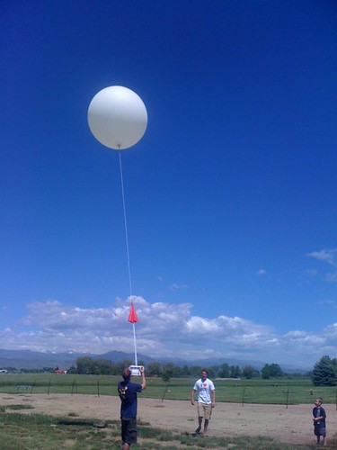
So to get a pictures of the curvature of the earth, you need exactly two things: a big balloon and a camera. But getting them back is the tricky part! Most people use a parachute to bring the camera back slowly, and a tracking device of sorts to locate the box once it has touched back down on the ground. Things get tricky because you don't know when to take the photo(s), and at an altitude of 30km (100,000ft), things get really cold. Really really cold. Like -50C (-58F) cold.
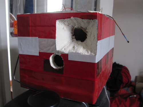
So people build big boxes out of styrofoam. And throw the electronics inside:
This is David's payload - pretty clean. After reading as much online information as I could find, I set off to build my own system.
Sensor System
The goal of the sensor array was to measure and record an entire flight. Most flights are on the order of 3-4 hours. Worst case, the flight could be as long as 5 hours. The goal is to measure as much as possible in the smallest space with the least amount of power as possible.
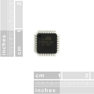
Processor: ATmega328 running at 3.3V. The ATmega328 is the really popular processor at the moment. It has a serial bootloader making it very easy to reprogram and a large base of example code. Along with this microcontroller, I used a 74HC4052 to multiplex the serial lines. It's a 1 to 4 mux for all the serial connections: GPS, logging, radio, +1 more (maybe add serial LCD someday).
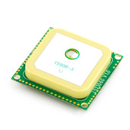
GPS: Locosys LS20031, 3.3V, Serial/4 wires. I love the LS20031. With a 5Hz update rate and a fast location lock, this GPS module is a work horse and works great. I do not yet know how it performs at altitude though. There is sometimes a limitation on GPS modules. When GPS was created, the US Department of Defense did not want other countries or individuals using GPS to do bad things like guide missiles (they kept that ability for themselves). Almost all non-military GPS units are crippled - the receivers won't work correctly at extreme heights or extreme speeds. It's a software limit on all civilian receivers to prevent us engineer types from using them for guidance systems. Civilian GPS use is fairly slow, and low altitude, so we rarely notice these limitations.
From the GPS Wikipedia page:
The U.S. Government controls the export of some civilian receivers. All GPS receivers capable of functioning above 18 km (60,000 ft) altitude and 515 m/s (1,000 knots) are classified as munitions (weapons) for which U.S. State Department export licenses are required. These limits are clearly chosen to prevent use of a receiver in a ballistic missile; they would not prevent use in a cruise missile since their altitudes and speeds are similar to those of ordinary aircraft.
Disabling operation above these limits exempts the receiver from classification as a munition. Different vendors have interpreted these limitations differently. The rule specifies operation above 18 km and 515 m/s, but some receivers stop operating at 18 km even when stationary. This has caused problems with some amateur radio balloon launches as they regularly reach 30 km (100,000 feet).
Since I want to use GPS for location and recovery only, the LS20031 should be able to handle both high altitudes and longitude/latitude at those altitudes. FWIW, our last reading came from an altitude of 17,259m (56,624ft) and it was performing swimmingly. I assume it continued to perform without problems.
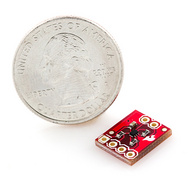
Accelerometer: ADXL345, 3.3V, I2C. I like working with the ADXL345. It easily gets basic accelerometer readings at 10Hz in three axis. And it has a plethora of features that I don't even begin to utilize fully. The goal here was to look at acceleration readings. What do the g-forces look like when the balloon explodes? How hard do we rattle the electronics around? The GPS should give us altitude so we can tell decent rates, but I want to know more. And a triple axis accelerometer will give us that.
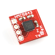
Magneto: HMC5843, 3.3V, I2C. The HMC5843 is low cost, easy to use, and just does its job of reading the earth's magnetic field in three directions. Why do we care? Well the accelerometer will give us force and shaking, but it may be difficult to tell our orientation in space. The magnetometer will give us an idea of where we are pointed (for example, facing north when we took picture X). We could re-create the acent/decent and look for spinning of the payload, etc.
Temperature: TMP102, 3.3V, I2C. (Notice how everything is on the I2C bus?) Capturing accurate temperature is actually kind of tricky. As battery voltages change and temperatures fluctuate, it's hard to get an accurate reading. The TMP102 is a saviour. It just works! I used two of these - one for the internal box temperature and one external to see how cold the world gets.
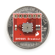
Pressure: BMP085, 3.3V, I2C. What I learned from David's launch is that he lost his altitude reading. Either because of a software glitch or the GPS module couldn't handle the extreme altitude. This was a major problem: you really must know the position and altitude of the balloon for accurate tracking. Without the altitude reading, is the balloon going up? Has it reached a max level? Is it coming down?! Oh no! Get going! So if GPS is going to fail at altitude, we can back it up with pressure.
The BMP085 is another one of those amazing sensors that, once up and running, work amazingly well. The BMP085 is capable of detecting a change of a few Pascals of pressure. This sensor is extremely accurate and has internal temperature compensation. The problem with all barometric pressure sensors is that they are relative pressure sensors. So if a storm comes through the area, the pressure can wiggle a lot. But this is ok for our purposes. We don't care what the pressure looks like as long as we can tell if it's increasing or decreasing. We can also linearly relate the instantaneous pressure readings to the GPS altitude readings. So if the GPS module flakes out for whatever reason, we can recreate (linearly extrapolate) our altitude based on the pressure. This is indeed what we saw from the limited readings we got the day of launch:
altitude(m) = pressure (Pascals)
1571 = 84491
2093 = 79354
3101 = 70681
4402 = 60448
5488 = 52715
9214 = 32047
14274 = 14712
16204 = 10776
17234 = 9415
As the altitude increased, the pressure dropped dramatically. I'm not sure what the pressure will look like at the top, but I assume the BMP085 can handle any pressure down to a near vacuum.
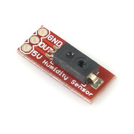
Humidity: The HIH-4030 is an easy to use humidity sensor with analog output, but is spec'd at 5V supply. The SHT15 is another humidity sensor that operates at 3.3V, but the SHT15 has a not-really-so-standard I2C protocol. And the HIH-4030 is much cheaper. Checking out the datasheet, the HIH-4030 is ratiometric to the power supply. This means that it can operate at 3.3V but the output will change linearly with the power supply. Ratiometric means that when the datasheet says that the sensor will output 2V at 40% humidity with a 5V supply, the sensor will therefore output (2V/5V = 0.4 * 3.3V = 1.32V) 1.32V at 40% humidity with a 3.3V supply. After some testing, the HIH-4030 works very well at 3.3V! But one problem with the HIH is that the sensor is so low power that the sensor doesn't output enough current to feed the ADC on the ATmega328. On future revisions of the main board I will use a capacitor or a current-follower so that the readings are a little bit more accurate. Why do we care what the humidity is at 100,000ft? Well do you know how humid it is up there? I certainly don't. I assume it's really cold and dry, but I wanted to prove it. So I included the HIH-4030 on this flight computer.
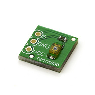
Ambient Light: TEMT6000 is a light sensor with analog output. It's basically a transistor that is biased by the amount of incoming light. The TEMT6000 doesn't give you a definitive amount, it's more relative. It can operate at 3.3V and attaches to an analog pin on the ATmega. Do we really care what the light level is inside the payload? Ok, perhaps not. But it's easy to include, and some day we may want to go further down this path to IR or UV light detection.

Battery levels: Using a voltage divider, we can monitor various battery levels. A voltage divider allows us to measure voltages that are greater than the voltage powering the system. For example, if the system is running at 3.3V, the ADC will return 1024 (maximum) for any voltage over 3.3V. Because the batteries should always be over 3.3V, we use a 10k/10k divider to cut this reading in half and then correct the reading in software. However, it gets a bit wacky as the voltage of the batteries drop below the output of the 3.3V regulator. If the battery is a 3.5V, 3.3V regulation is not a problem. But when the battery is at 3.0V, we will need to use the internal band gap on the ATmega328 to tell where the battery voltage is at. Knowing the battery level of the payload is an important metric. If the lithium polymers are at 4.1 to 3.6V, everything is fine. As the voltage drops below 3.6V you know you are outside the 80% capacity and you're quickly running out of power. Knowing youre approaching battery death could change the way to track the balloon. But we should have ample battery power!
Datalogging: OpenLog, 3.3V, 3 wires/serial. I am completely biased and partial to the OpenLog. I created it so I'm really comfortable using it. But it's so simple to use! The OpenLog is another ATmega328 that sits there monitoring a serial pin. All we have to do is throw a serial stream of data out the serial multiplexer and the OpenLog will diligently record this information to SD. This is an important part of the payload. I want to take a large amount of measurements and record them for later analysis. The OpenLog board plugs onto the flight computer and seamlessly records anything the flight computer outputs as a printf or Serial.print() statement inside an Arduino sketch.
Buzzer: We may want a buzzer on board to start beeping. The idea was once the altitude is below a certain level or if the overall flight timer hits a threshold (like 5 hours) then start beeping. This would help in finding the payload. In practice, this was a bit of a silly idea. The eastern plain of Colorado is huge. We could put a bull horn on there and it would still not be loud enough to find the payload by sound.
If this is starting to sound like a giant SparkFun ad, I apologize. But this is what I love to do! It's rare that I actually get to play with the cool toys around me. The balloon project was a good excuse to layout a new PCB...
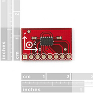
The Flight Computer

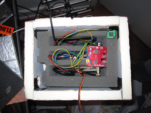
Working at SparkFun with a production floor and access to SMD soldering - I'm fairly spoiled. On top of that, I love laying out PCBs. So here you can see the Flight Computer. It's not really a full computer, but it is a very small, light, embedded system capable of measuring a large amount of sensors multiple readings a second. Slap on an OpenLog and you've got a fairly lightweight data logger. The flight computer needs the ability to check the current GPS long/lat and communicate that with the ground.
Using the 74HC4052, we are able to tie one UART on the ATmega328 to four different serial devices. Serial multiplexing is easy if you're not as worried about missing incoming/outgoing packets. For example, we don't need to capture every GPS NMEA sentence. We can flip to that serial channel, listen for a bit, grab the location, then move to the radio channel to broadcast the location, then flip to the OpenLog and record the full GPS and sensor record, then flip to the radio and broadcast out the pared down GPS location, then repeat.
I really enjoy the small size and good secure connection of these vertical 1mm pitch SMD connectors. Instead of creating my own cables (crimping is nearly impossible at that scale) I cut and spliced onto the EM408 long cables. It worked really well. 5 pins are adequate for I2C sensors and for serial devices. The red heat shrink is just there to keep the wires grouped together. The hot glue on the LS20031 and TMP180 breakout is there for stress relief (the wires are pretty thin). The right angle male connector sticking out the bottom of the GPS module worked two fold: first so that I could attach a serial to USB board to reprogram the unit to output only the GPGGA sentence (easier parsing in firmware). And secondly, the pins could be shoved into the styrofoam enclosure making sure it didn't move (you want the GPS module always pointing up).
What are those green wires next to and underneath the OpenLog? Oh nothing, I just got my TX and RX lines swapped (what an amateur I am). Anyone can layout a PCB. It takes someone with skills to make a bad PCB functional.

The PCB layout (with lots of fixes) is available for your perusal. The schematic, Eagle files and source code are all released under the creative commons share alike v3.0 license. Use it as you wish. Please give us attribution if you do. I'm fairly proud of the source code as it's one of the more complex projects I've coded. While my coding style/standards could use some help, I believe it to be a good set of example code for the BMP085, ADXL345, HMC5843, LS20031 GPS parsing, TMP102 I2C temperature interfacing, analog to digital conversion, serial multiplexing, and general EEPROM user setting reading/writing.
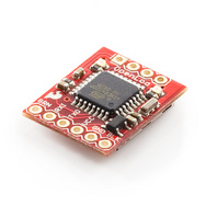
Radio System

The craziest thing about balloon tracking are the distances. I've used various low power radios to transmit a packet or two across the room, but with a balloon at 20 miles up, you need a different type of radio. While there are some significant resources for HAM radio operators, I don't have my license nor the equipment. After reading on an amateur balloon website, I chose to use the Digi XTend 900MHz 1Watt transceiver. This was the most powerful radio I've played with. It claims to have a 40 mile range, but that is line of sight and in theoretical conditions (no interference). The radio needs 5V for maximum power and may use up to 800mA when transmitting at full power. It doesn't require a HAM license which is a plus. And 40 miles should be enough, right?


I used two 3.7V lithium polymer batteries, 2000mAh each, and a breadboard SMD power supply (these things are awesome!) to regulate the nominal 7.4V down to 5V for the radio. This worked well, but the regulator gets toasty. This is not a bad thing. In the beginning, I thought I was going to need a heating system for my payload. The radio gets very toasty as does the regulator (LM1117) on the SMD power supply. These two heat sources provided more than enough exothermic energy to keep the inside of the box above freezing. The hair band makes a great way to keep the bulk together while you're inserting/extracting the system from the payload.

You can see in the picture I modified the SMD power supply: removed the barrel jack and switches, added two JST connectors for easy battery disconnect, and I jumpered across the on switch so that the board was automatically on if the batteries were attached (I don't want the radio accidentally turning off!).
I did find over the course of testing a few interesting 'gotchas'. I originally wanted to power the radio from the main sensor board. The radio, when transmitting, sucks a ton of current for a short amount of time (a few hundred milliseconds). Even with ample capacitor decoupling (1000s of uF), the radio kept causing GPS lock problems, and caused the main sensor board to reset every time we sent the radio serial information (which caused a transmission and subsequent power draw). The answer was to power the radio by itself. This allowed me to power the radio at a full 5V, resulting in increased radio transmission power and range, but the SMD power supply is linear (fairly in-efficient). Not a horrible trade-off. Of course all this power supply madness happened the night before the launch.
Another problem was the 5V radio and the 3.3V GPS receiver. When I powered the radio at 5V and attached it to the sensor board, I lost serial reception from the GPS module. I believe the 5V TX pin on the Digi radio was overpowering the 74HC4052 serial multiplexer. Either the Digi radio TX pin was overpowering the GPS TX line or the ATmega couldn't hear the 3.3V line changing with a 5V TX line in the background. I'm not sure and didn't have the chance to probe deeper. But the solution was to disconnect the Digi Radio's TX pin. While the payload was still able to send serial data out to the radio and down to the base station, the disconnected TX line would dis-allow any transmission from the ground up to the balloon. This would prevent any cut-down command. That was acceptable because I had already thrown out the cut-down system at this point, but for any launch in the future I really need to get this two-way communication restored.
The Digi modem radios were setup for 9600bps. I looked into the sleep modes and various packet modifications in the datasheet, but since I had ample battery power to run the system for ~10 hours, I didn't want to risk limiting the reception range with timeouts and sleeping radios. 9600bps does improve the transmission range and that was fine - I didn't need/want to transmit that much data. In the future I will use a different radio system and I am fairly confident the XTend modules are doing significant overhead on the 900MHz carrier to try to insure packet delivery. I don't care if I missed a character or two, I needed reception until the very end (humans are pretty good at piecing together bits of data out of a few glitches). As David phrased it, my radio was doing TCP/IP and I needed UDP. In the future, I hope to use a radio that just blasts out the data, use HAM equipment to use a headset to audibly locate the balloon in the air, and possibly use a cellular backup (send a text message every 15 minutes with long/lat - although cellular reception can get really spotty in eastern Colorado).

For antennas, I looked for the cheapest source for 900MHz antennas that had the highest dBi rating. While SparkFun does sell 900MHz duck antennas, they are small and I had room for something larger. I found a site called L-com and decided on the RE9-5U-SM 900MHz magnetic mount omnidirectional antenna with SMA male connector. These antennas are not too expensive at $20 each. This specific model required an adapter to adapt from the SMA male connector to the RP-SMA connector on the Digi radio. I had to do this because the antenna with the correct RP-SMA connector was backordered at the time.
I bought two antennas - one for the payload, one for the car base station. They worked pretty well but there were a few problems. The antenna to go in the payload had a lot of extra cable that took up a lot of room inside the payload box. The magnet embedded into the base of the antenna added unneeded weight to the payload. I could have tried to remove these two parts but I was afraid any modification to the cable or connectors would cut down on transmission distance and that was the last thing I wanted, so I dealt with it every time I packed the payload (grrr). The payload antenna would eventually be taped to the bottom of the payload box, pointing down. This would maximize transmission distance, but would obviously try to stick into the ground when it's landing. Not great but no other solution was thought of. The other problem was the 4' length of cable on the antenna and reception in the car. 4' is just enough to get from the roof to the inside of the car making the cabling and laptop setup in the car cumbersome. 10' of cable would have been great. I may order an extension cable for the next go around.

The base station inside the car was pretty simple. Just the radio, attached to a USB to serial converter board (FT232R Breakout), inside a SparkFun enclosure box. Build it solid. You don't want to be fidgeting with your radio receiving while the balloon is in flight. I ended up zip tying the USB cable to the enclosure because the miniUSB cable would become disconnected silently - all I would see is that the balloon would stop transmitting! Bad. Again, make sure the base station electronics are solidly connected together.
Distance test! Before you launch anything, setup the radio or payload to transmit GPS data every few seconds. Put it some place safe (like in your car) and free from as many visible obstructions as possible, and start walking with the base station and a laptop. I felt a little weird walking down the street with a laptop out and an antenna on my backpack, but I was able to get about 1.5 miles away from my car, in a straight line, with only cars and light poles in the way before I lost reception of the payload. While this was a little disconcerting (1.5 mile range from a 40 mile radio?) I knew that buildings, cars, and people degrade signals significantly. Once the payload and antenna were in the air, there would be nothing blocking the transmission. And this turned out to be true. On launch day we were about 10 miles behind the balloon when it was 10 miles up - giving us a reception range of about 15 miles before reception became intermittent.

Because I was a afraid the little 900MHz antenna wasn't going to do so well, I decided to order a Yagi-Uda antenna to be used on the ground. I know Yagi's are directional antennas, but it should improve the reception significantly (from 5dBi to 12dBi). So I ordered the HG912YE-RSP 900MHz 12dBi Yagi Anntenna RP-SMA from L-com as well as a backup. Unfortunately doing my 1.5 mile walk/range test, the reception wasn't noticeably better! In the end, the regularly magnetic mount omnidirectional antennas worked very well, but it was the lack of roads that eventually got us in trouble.
While the payload was lost, we did record a range of readings transmitted by the payload. It's not all the measurements, just a select few for tracking the payload (long, lat, altitude, pressure, temperature, and battery levels). I didn't want to transmit everything as that would severely clog the RF link as the balloon approached the edge of transmission range.
Next page - Still and Video cameras
High Altitude Balloon Page:
Is there a shopping list, or something similar, somewhere that would have everything needed and costs? A few other students and I are building a high altitude balloon with one of our teachers, we want to put a sensor package on it, but don't know everything that we would need. (don't want to end up ordering everything but one cable or something, and have to pay extra shipping or delay launch) Thank you.
There isn't, especially since it looks like a custom board was used. Try emailing techsupport@sparkfun.com and they can help you figure out what parts you might need for your application.
thanks
So I have downloaded the schematic and pcb files for the telemetry board. Is it just me or is there an assumption on how the openlog connector traces connect to the multiplexor? I would love to be able to submit the file to batchPCB to get a working system and then modify from there. Not trying to be a prick but it seems there are a few projects on here that have some things cut out and left to the users/buyers imagination. I'm cool with that but let me know up front please. The tutorials are great and I'll buy as much as I can through sparkfun knowing I am paying more than digikey or mouser. But... I don't know... is it a liability thing? then let us know.
figured out the openlog connectors. will remove foot from mouth. sorry
How would you go about implementing the software? I know basic C++
Hey Nate, could you attach your code for the 9xtend transmitting I have been looking at the data sheet for awhile now and still haven't had any luck. Thank you.
What controller/computer did you use for the sensor board?
going along with the Ham radio idea, you could use an audio sound module connected to the input of the radio to transmit the data in as actual "words". that would be VERY cool.
BobK's suggestion of APRS is a good one. It's pretty easy to have a 10km to 20km range on the ground, and in the air 50km to 100km should be pretty easy without breaking a couple of watts. Lots of receiver choices, fairly good repeater and internet gateway coverage already on the ground, and two way communication capable. It is well enough suited that it actually already has a "this is a balloon" identity code available in the protocol. It can also handle telemetry packets, in case you want some of the other measurements relayed to the ground during the flight.
But the real reason I want you to try it:
The rest of us could then watch the flight path online, live!
Suppose that I wanted to repeat something similar, but I wanted to fix up the behavior of the HIH-4030 humidity sensor when running on a 3.3 V supply.
Would a standard LM358 opamp connected as a voltage follower to buffer the analog voltage output from the HIH-4030 before it goes to the AVR do the trick?
I'd have two radios in the unit; the first being the microwave high-bandwidth one described above, and the second being an HF beacon for a locator, which would do something like transmit a different digit of its lat/long every 5 minutes or so. I'd use an omnidirectional antenna here, vertically polarized. You could also use an APRS locator but I am not sure how well APRS stuff works when you have a need for great distance and low power consumption.
Directly soldering, instead of using connectors, will increase reliablity. Failing that, use good quality brass connectors.
The problem with using off-the-shelf, part-15 hardware is that everyone else is ising it too. You need to some quiet radio spectrum. This is where ham radio comes in handy; there's lots of spectrum in the microwave region which is fairly quiet. You could transmit real-time video here and not crowd other signals out. At higher bandwidths, of course, antennas are smaller. I've thought of using a yagi, with element spacing accomplished by weight on a line from the balloon, but then the elements themselves might not be stable. You might want to try a circularly polarized yagi, with circular elements so the polarization problem is eliminated, but then there's some weight being added. But it may not be worth worrying at all, if you're at 10 ghz the directional antennas you can use can be very small, and don't have to be the string-supported yagis I describe.
You're not going to find a bigger fan of the Bosch BMP085 pressure sensor (it's at the heart of the Jolly Logic altimeter, which is the fastest selling altimer right now), but unfortunately for your 100K foot goal it's rated to just 9000 meters (29,527 feet). I'd love to hear that it works above that, of course.
Checkout the data (in the tutorial above) we received before we lost contact with the balloon. The BMP085 is awesome and continued to give us data at 52,000 feet. Last reading was 9415 Pascal read at 17234m.
I use the Digi Xtend radio on my flights. The thing I discovered was the breakout board with the zigbee connectors was not reliable. I ended up soldering directly to the radio pins.
Getting bounced around under a balloon will dislodge a lot of things. Best to eliminate all the connectors you can
Good point. I would have to have the breakout board slip off and loose radio reception. I will probably commit and solder directly to the radio on the next launch.
I'd like to find out more about the serial bootloader Nate uses on the ATmega328. Do these chips come pre-loaded with the bootloader? And will this feature lock up the serial port for other uses? Can you debug and single step through code this way?
I've always programmed micro's through the JTAG interface, but it seems like everyone these days (especially in Arduino) programs through the serial port. I've never tried this. Can someone fill me in on how this is implemented?
I have some of the same questions and several other very novice questions.
I'm a beginning electronics student and am starting work on a HAB project using Sparkfun's HAB board. My newbie question is: how do i talk to this board? I have no problem digging into code, but would very much like to find out the best way to access the data stream coming from the sensors. My goal is to get this board to log to files on an SD card, and would much appreciate any help that anyone can throw my way!
Thanks!
The range problem with the radios was likely due to your choice of antennas. The magnetic base whip antennas are designed to be operated over a ground plain (i.e the roof of your car). The styrofoam box was not providing a proper ground plane for your payload antenna. In this case, the rubber duck antenna would have been the better choice (its a dipole and doesn't require a ground plane). The big jump in range between your walking ground test and the flight day was probably because your base station antenna was on the roof of your car and not stuck to the top of your backpack. The other issue is polarization mismatch. If you mounted the payload antenna parallel to the ground and the base station antenna vertically on the roof of your car, the 90 degree polarization mismatch cost you big time. As previously suggested use a circularly polarized antenna that does not require a ground plane.
Great project! Thanks for sharing.
Very interesting read! Spotted one grammar error "line of site" instead of "line of sight" :).
I've flown the 9Xtend modules for quite some time (ever since they were introduced) on high altitude balloons and even on a Rockoon (rocket launched from a balloon). As pointed out on another post, the radiation pattern below a vertical whip is the null point and at 100,000 feet can give you a null zone of 20 miles in diameter or more. I solve that by using a "Nano-Wheel" antenna which is a horizontally polarized omni pattern cloverleaf antenna that gives a good hemispherical pattern below the payload. It's available from: http://www.hamtv.com look for the Olde Antenna Labs section. Of course you'll have to mount the ground antenna in a horizontal configuration when using this system.
I use the Cypress PSoC for my balloon tracking telemetry transmitter with built-in Inventek GPS: http://www.elktronics.com or http://www.wb8elk.com
Cell phone GPS tracking does not work very well due to the very nature of the GPS tower system. Ever try to make a cell phone call from a mountaintop? Same problem only much worse from a balloon. A GPS cellphone tracker will only work as a backup recovery locator in the lucky case when it manages to make a position report just prior to or just after landing. They rarely work above a few thousand feet.
- Bill Brown WB8ELK
It's not surprising that your package stopped updating around 57,000'. The DoD restriction on GPS signals call for the GPS module to stop sending updates if they go above 60,000' and 1,000 knots. Unfortunately, the rule is a bit ambiguous, so a most manufacturers interpret this as "OR." The Trimble Copernicus is known to work, and the "Inventek High Altitude Build" is also good.
Your antenna could also be another problem. Using a "high gain" omni means that you are flattening out the radiation pattern. This is desirable if you are trying to cover your whole school with WiFi,. but it effectively extends the "cone of silence" underneath the balloon. It's likely that you could not receive the signals at all if you were within a few miles of it.
Also, you should really consider putting a secondary transmitter on there, so that you can use good-old-fashioned DF (direction finding)to locate the box when the GPS/Computer/etc fail. Power this TX with a separate, non-rechargeable Lithium battery and maybe make it a separate package with a different antenna design.
Good luck!
Arclight
23B Hacker Space
http://shop.23b.org
One thing to keep in mind about "omni" antennas. The radiation pattern is more like a toroid, with max radiation around the sides and minimum radiation on the top and bottom. So if you mount the antenna on the bottom pointing downward, you will have the poorest signal level directly underneath the balloon. Also, the higher the dBi rating of the antenna, the flatter the toriod, and the area of bad reception on the top and bottom becomes greater. For your application, it may be tetter to use a 1 dBi "omni" antenna.
One other thing: please don't use cellular technology in the air... check this out. From CFR Title 47, Part 22, Subpart H:
? 22.925 Prohibition on airborne operation of cellular telephones.
Cellular telephones installed in or carried aboard airplanes, balloons or any other type of aircraft must not be operated while such aircraft are airborne (not touching the ground). When any aircraft leaves the ground, all cellular telephones on board that aircraft must be turned off. The following notice must be posted on or near each cellular telephone installed in any aircraft:
?The use of cellular telephones while this aircraft is airborne is prohibited by FCC rules, and the violation of this rule could result in suspension of service and/or a fine. The use of cellular telephones while this aircraft is on the ground is subject to FAA regulations.?
I'm really surprised that you had trouble with the 9xTends. I managed a team that flew (and still does) those radios for years with 100% recovery (I was invloved in ~75 launches). One thing that I wonder about is your RF data rate... the 40 mile spec is for 9.6k RF rate, which is a very different setting from the interface data rate. If you had the radios set to the 115k RF rate and the 9.6k interface rate, you would experience a degradation in link margin.
FWIW, we used one of these http://www.antenna.com/apg_products.cgi?id_num=11132 mag mounted to the roof of a car for recovery, and a circularly polarized patch antenna on our payload.
I'm planning a balloon project with the XTends. Do you have any more info on your antenna setup? Specifically, how your car antenna is mounted / oriented, and perhaps a link to the circularly polarized antenna you used on your payload?
I suggested a megasensor breakout - basically what you have though I might add a gyro, all I2c, split the analog and digital supplies for low noise with capacitors and isolation (e.g. ferrite beads) where appropriate.
Accelerometer - the ADXL345 or the new Bosch.
Gyro - the new 3 axis one you carry (probably not for balloon, but who knows).
Baro+TEMP - SCP-1000. - I think the bosch you use might also do temp.
Magnetometer - the HMC5843 you have above.
(I don't know about humidity, I have a self-contained module that does variable capacitance - linear from about 120-190pf from 0 to 100% - so could be used in an oscillator and run at 3.3v - and you do have I2C capacitance chips as well).
4 wires and you get all these sensors. And you might be able to add a few more.
I might also add a RTC like one of the Dallas TXCOs so would be 2ppm and you get precise time even without a GPS lock.
GPS - also 3.3v, but not I2C.
why not use the 3.3V/5V logic converter for the radio?
I could have but it would have added more complexity. Since the ATmega328 could handle the 5V signals, I skipped it. Will have to revisit the entire system on the next launch and will probably include at least an inline resistor.