
Tri-Color LED Breakout Quickstart Guide
Overview:
Brighter than the LED Starter Kit but not quite packing the punch of the über bright Luxeons, the Tri-Color LED Breakout Kit lets your geek shine. If you need something large, bright, and colorful to cast your project in the best light, look no further than the Tri-Color LED Breakout Kit. With superbright LEDs it can blind brighten just about anything! Here we have everything you need here to get you up and running with it quickly.
Requirements:
- soldering iron
- solder
- cutters
- male headers or other connection method
-
(optional) needle nose pliers -
(optional) third hand
Since the Tri-Color LED Breakout is simply a breakout there are many, many ways you can use or control it. However, for this guide you will find the following helpful:
- breadboard
- jumper wires
- Arduino
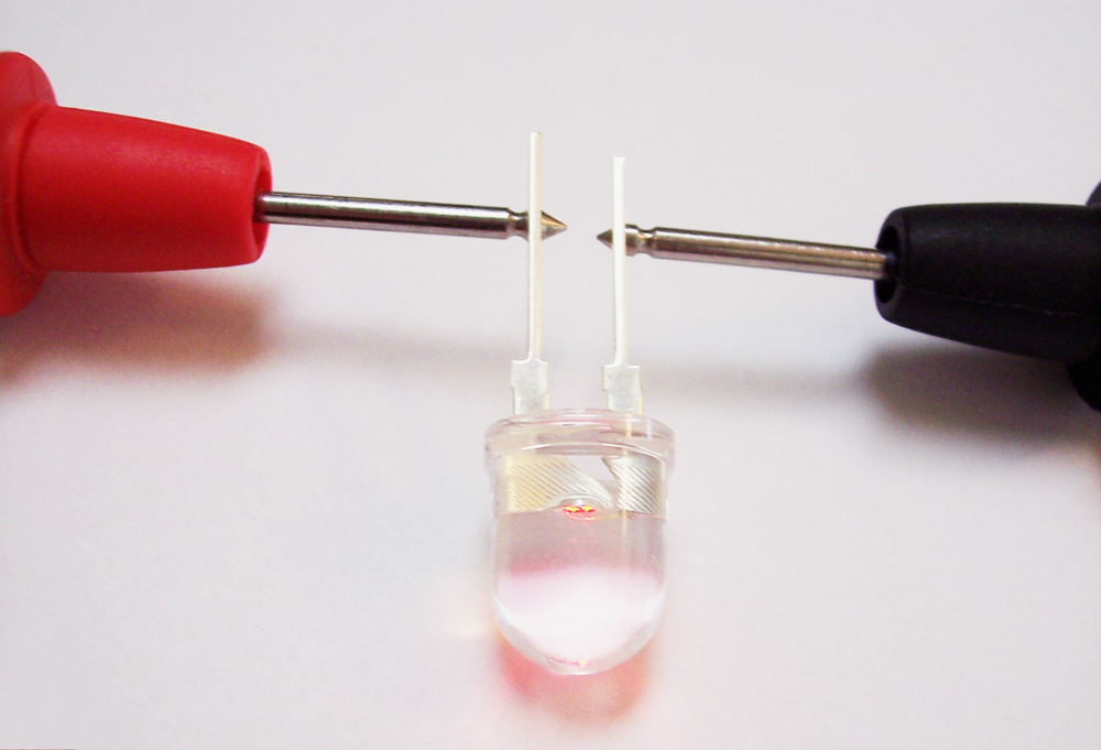
- (optional) multimeter or coin cell battery
What it Does:
The Tri-Color LED Breakout Kit is a simple kit designed to allow control of very bright LEDs which draw more current than the pins of a microcontroller can provide. Each LED has transistor to switch the 5V source to the LEDs. There is also a current limiting resistor to drive each LED as close to their 80mA maximum as possible. Check out the schematic to see it all laid out.
How to Use it:
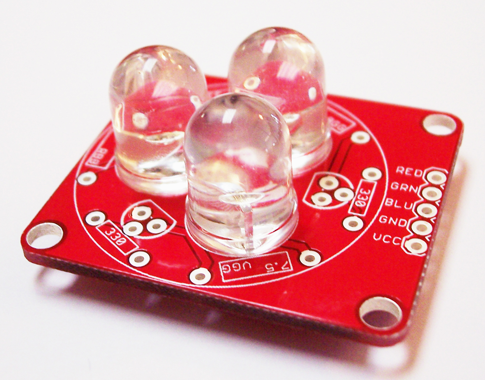
Assembly:
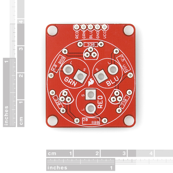
- 1x Tri-Color LED Breakout PCB
-
1x Super Bright LED - Red 10mm -
1x Super Bright LED - Green 10mm -
1x Super Bright LED - Blue 10mm -
1x Resistor 7.5 Ohm (Stripes will be colored: Violet, Green, Gold, Gold) -
1x Resistor 6.8 Ohm (Stripes will be colored: Blue, Gray, Gold, Gold) -
1x Resistor 20 Ohm (Stripes will be colored: Red, Black, Black, Gold) -
3x Transistor 2N3904 -
3x Resistor 330 Ohm (Stripes will be colored: Orange, Orange, Brown, Gold)
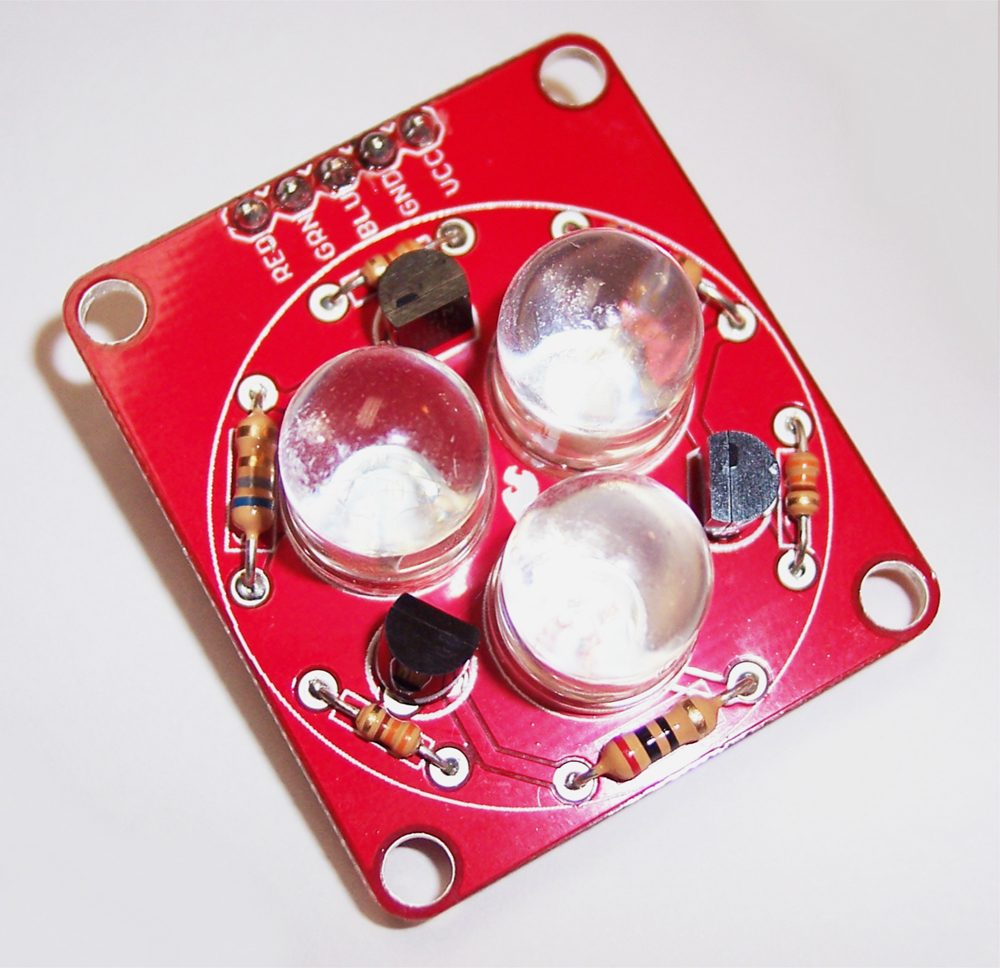
Alright, let's begin building!
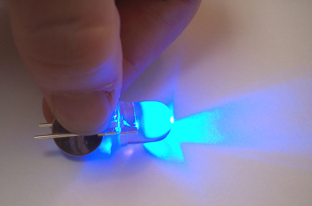
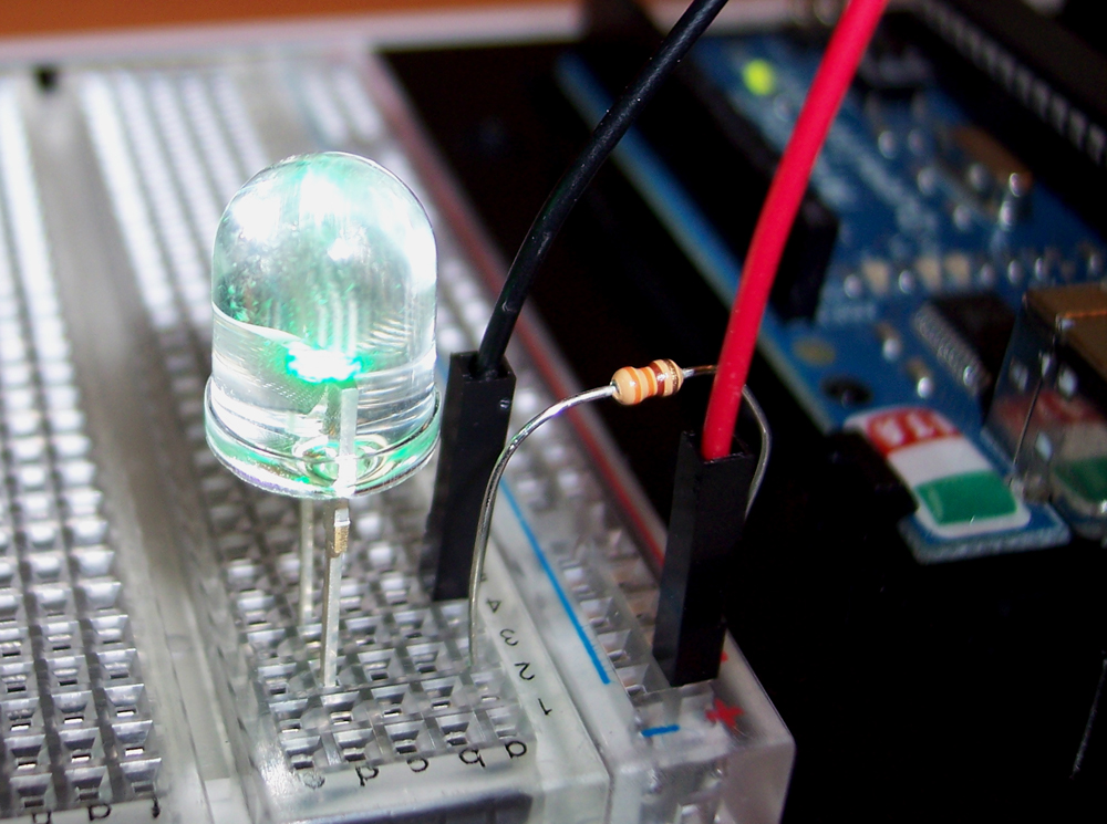
Now you need to figure out which color each LED is. There are a few ways to do this:
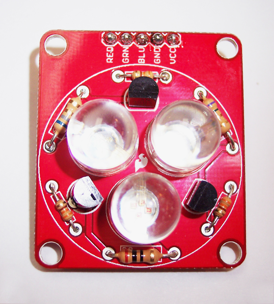
Next, it is time for the transistors. Transistors are used because these LEDs will be running at their maximum brightness around 80mA. That’s more than a typical microcontroller, like Arduino, can output on a pin. So, we use transistors to switch the LEDs on and off. Line the transistors up with their footprints. A little wiggling should get them as close to the board as possible. Then solder and clip their leads.
7.5 Ohm (Violet, Green, Gold)
6.8 Ohm (Blue, Gray, Gold)
20 Ohm (Red, Black, Black)
330 Ohm (Orange, Orange, Brown, Gold)
Finally solder on a connector. We choose to use male headers for use in a breadboard but you, of course, are free to use just about anything you please.
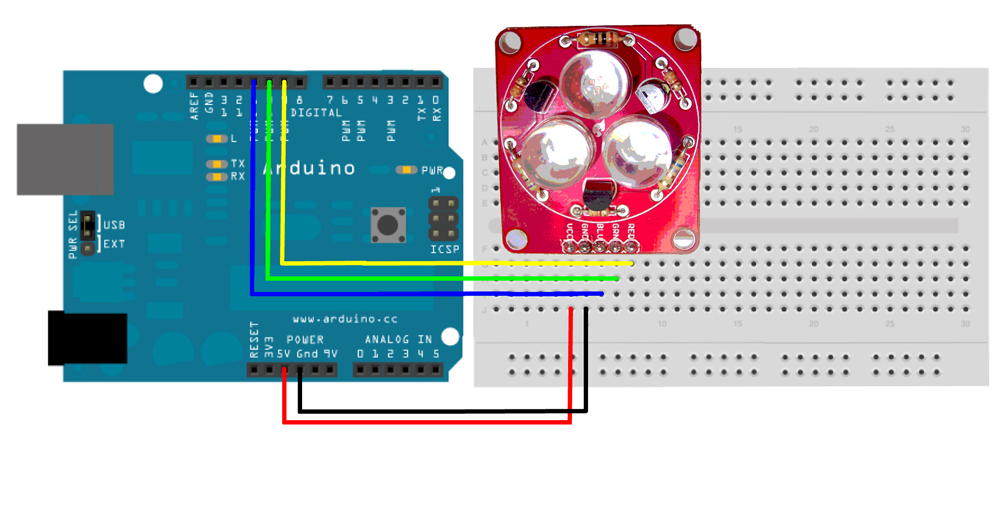
Hardware:
Firmware:
Now that everything has been hooked up, we're ready to control it with our Arduino. First, you will need to install the Arduino IDE if you haven't already. This will allow us to load example code and control our LEDs. Check this tutorial if you need more help installing the Arduino IDE.
300px;overflow:-moz-scrollbars-vertical;overflow:-moz-scrollbars-horizontal;overflow-x:auto;overflow-y:auto;background:#CCCCCC;border:2px outset black">
 /*
 Tri-Color LED Breakout - An example sketch for the Tri-Color LED Breakout
 By: Hilary Hoops
 SparkFun Electronics
 Date: 6/23/11
 License: CC-BY SA 3.0 - Creative commons share-alike 3.0
 use this code however you'd like, just keep this license and
 attribute. Let me know if you make hugely, awesome, great changes.
 */

int RedLED = 9;     // LED connected to digital pin 9 (pwm pin)
int GrnLED = 10;    // LED connected to digital pin 10 (pwm pin)
int BluLED = 11;    // LED connected to digital pin 11 (pwm pin)
int LED[3]={RedLED, GrnLED,BluLED}; //an array to make it easier to cycle though
the LED colors

void setup()  {
  //Set pins as output pins
  pinMode(RedLED, OUTPUT);
  pinMode(GrnLED, OUTPUT);
  pinMode(BluLED, OUTPUT);
}

void loop()  {
  //Fade each LED in and out individually. Possible range is 0-255
  for(int i=0; i<3;i++){ //Cycle LED color
    //Fade in
    for(int fade=0; fade<=255; fade+=5){
        analogWrite(LED[i], fade);
        delay(30);
    }
    //Fade out
    for(int fade=255; fade>=0; fade-=5){
        analogWrite(LED[i], fade);
        delay(30);
    }
  }
  //Fade all the LEDs in and out
  //Fade in
  for(int fade=0; fade<=255; fade+=5){
      analogWrite(RedLED, fade);
      analogWrite(GrnLED, fade);
      analogWrite(BluLED, fade);
      delay(30);
  }
  //Fade out
  for(int fade=255; fade>=0; fade-=5){
      analogWrite(RedLED, fade);
      analogWrite(GrnLED, fade);
      analogWrite(BluLED, fade);
      delay(30);
  }
}
</div>
That should be all you need to get your lights shining.
Resources:
- Tri-Color LED Breakout Kit Product Page
- Basic Explanation of LEDs
- LED current limiting resistors
- Anode vs Cathode
Conclusion:
And then I had noticed that the poor thing was screened wrong. It should be screened the same on both sides. Top and bottom.
Also a special sound set towards your demo sketch author. The person wrote one which only needed one thing changed. For some strange reason a select, and copy to clipboard and then pasting inside the IDE caused the comments to be broken wrong in spacing. Fixed with a judicious delete on spacing..... Also means that the code contained in the repository needs to be checked....
Interesting idea for the LED positioning scheme. L for the long lead, and S for the short one. Took me for a fast loop.
This really confused me as well and your comment above about the comment line break missing (or an additional line comment on the following line) is still an issue.