
Triple Axis Magnetometer - HMC5883L Breakout Quickstart Guide
Overview:
This is a breakout board for Honeywell's HMC5883L, a 3-axis magnetometer. Magnetometers have a wide range of uses. The most common include using the chip as a digital compass to sense direction or using them to detect ferrous (magnetic) metals.
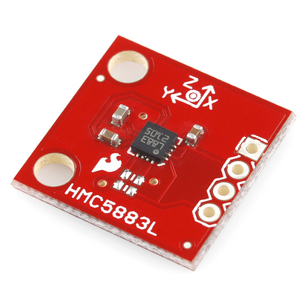
Triple Axis Magnetometer Breakout - HMC5883L
Requirements:
This breakout board can be hooked up to a number of microcontrollers, as long as they have an I2C interface . However, for this guide you will find the following helpful:
- Arduino Uno
- Breadboard
- soldering iron
- solder
- male headers or other connection method
- (optional) needle nose pliers
- (optional) third hand
How it Works:
Magnetic fields and current go hand-in-hand. When current flows through a wire, a magnetic field is created. This is the basic principle behind electromagnets. This is also the principle used to measure magnetic fields with a magnetometer. The direction of Earth's magnetic fields affects the flow of electrons in the sensor, and those changes in current can be measured and calculated to derive a compass heading or other useful information.
How to Use it:
So you're ready to start using this chip with your Arduino are you? Well lucky for you, we have everything you need to get your project rolling.
Hardware:
First we'll need to solder on some headers to the breakout board so it will fit into a breadboard. For soldering suggestions, this tutorial is helpful.
The breakout board includes the HMC5883 sensor and all filtering capacitors necessary. There are two unpopulated pads in case you need pull up resistors (no need for them if you're using the Arduino/ATmega328).
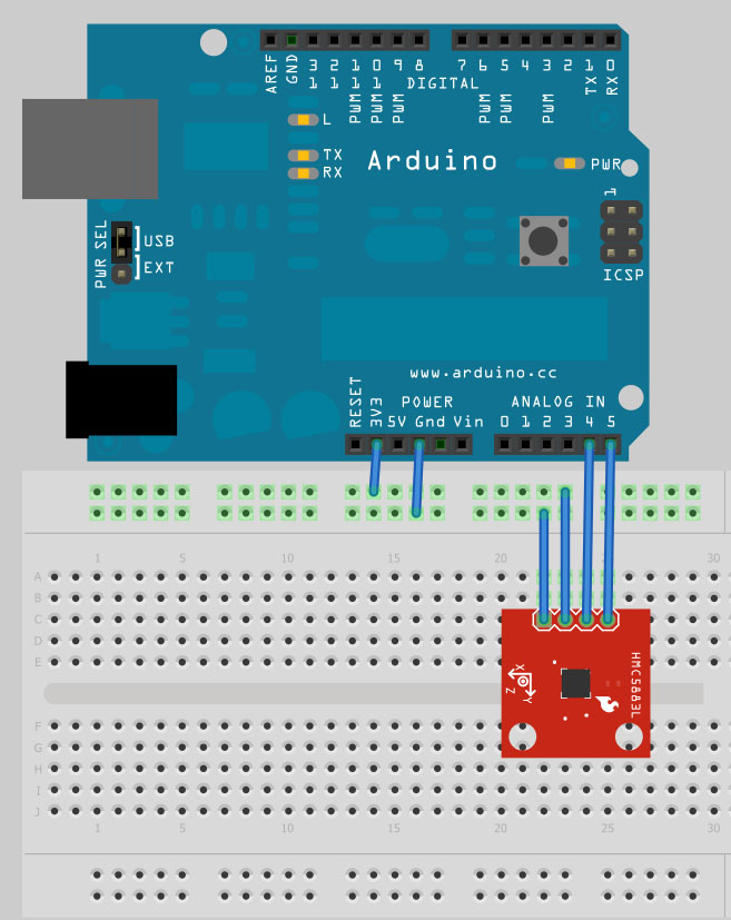
Communication with the HMC5883 is simple and all done through an I2C interface. We will go into this in further detail momentarily. All you need to know for now is how to wire it up. Attach the SDA line to A4 and the SCL line to A5. Also attach Vcc to 3.3V and GND to GND.
Software:
If you haven't done so already, please download and install the Arduino IDE.
Firmware:
The HMC5883L speaks a kind of funky serial language called I2C. I2C requires just two wires for communication – one for a clock (SCL), and one for data (SDA). Be aware that you probably should avoid using those two pins for anything else (except for maybe other I2C devices, if you want to get tricky). Don't try using them as analog inputs!
![]()
The Arduino code example we have, HMC5883.pde, will continuously reads data from the magnetometer for each of the magnetometer's axes using I2C. If you need help uploading the sketch to your Arduino, their site has lots of helpful information.
Let's take a look at the first part of the code:
    #include <Wire.h> //I2C Arduino Library

#define address 0x1E //0011110b, I2C 7bit address of HMC5883

void setup(){
  //Initialize Serial and I2C communications
  Serial.begin(9600);
  Wire.begin();

  //Put the HMC5883 IC into the correct operating mode
  Wire.beginTransmission(address); //open communication with HMC5883
  Wire.send(0x02); //select mode register
  Wire.send(0x00); //continuous measurement mode
  Wire.endTransmission();
}
The code that resides within the setup() function is ran once at the beginning. It initializes the serial communication at 9600 baud. We use the serial communication to send data for each axis back to the computer. The I2C is also initialized. We then do a 'write' operation to the HMC5883L. The purpose of this 'write' operation is to adjust the value in the configuration register of the HMC5883L to tell it to be in continuous operation mode. This lets us make continuous reads of the axis data. By default the chip is in single read mode meaning after reading from it once, it will go idle to save power. Once idle, we have write to it to turn it on before we can read from it again. The datasheet has all the information about the registers in addition to other useful information. Of course, we always encourage you to RTFM... just look at the datasheet...
Moving on, here's where we actually request and receive the data:
    void loop(){

  int x,y,z; //triple axis data

  //Tell the HMC5883L where to begin reading data
  Wire.beginTransmission(address);
  Wire.send(0x03); //select register 3, X MSB register
  Wire.endTransmission();


 //Read data from each axis, 2 registers per axis
  Wire.requestFrom(address, 6);
  if(6<=Wire.available()){
    x = Wire.receive()<<8; //X msb
    x |= Wire.receive(); //X lsb
    z = Wire.receive()<<8; //Z msb
    z |= Wire.receive(); //Z lsb
    y = Wire.receive()<<8; //Y msb
    y |= Wire.receive(); //Y lsb
  }

  //Print out values of each axis
  Serial.print("x: ");
  Serial.print(x);
  Serial.print("  y: ");
  Serial.print(y);
  Serial.print("  z: ");
  Serial.println(z);

  delay(250);
}
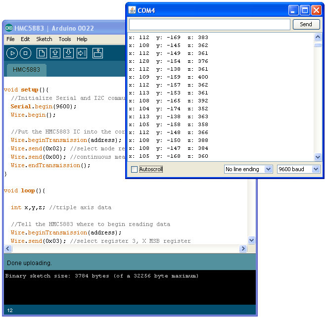
The loop() function will run over and over again as long as the board has power. Each time through, we do a quick write to tell it where we want to begin reading the data for the axes. Register 3 is selected and happens to be the most significant byte of the X axis. We request to read 6 bytes one by one. The chip auto-increments the number of which register we are reading from so we don't have to select each register manually before we read from it. The x, y, and z axis data is then sent back serially to the computer. You can see these values by using the 'Serial Monitor' of the Arduino development environment as shown below.
All you need now is a creative idea of how to use this information in your next project. Always feel free to share it with us, it just might end up on the Sparkfun homepage!
Resources:
Conclusion:
Enjoy your new magnetometer! If you have any problems, feel free to contact SparkFun Technical Support at techsupport@sparkfun.com
What are the units that you're displaying?
Sparkfun should also break out the SRDY pin for this chip (making it a 5 pin 'project' versus 4.) The SRDY pin does not need to be used, but if it is not made available it cannot ever be used, and it is the means (an interrupt line) by which to read samples from the device much faster than mere serial operations and polling would permit. Such a simple thing, wish they had done it on the first pass.