
"Laser Limbo"
Brainstorming for Open House 2011
Sometime around mid 2011, Sparkfun had the idea of holding an Open House as a fun event that would give us the opportunity to interact with the community. We brainstormed many fun ideas for the event and decided on which ones to shoot for. During this process of brainstorming, the education team, came up with the idea for “Laser Limbo.” We wanted to create an electronic version of the classic limbo game.

With that idea in mind, we knew what we wanted to accomplish, but it was time to figure out how to actually make it reality. There were many methods and ideas that were contemplated. Everyone really liked the idea of using an actual laser and mechanically moving the laser up and down. However, given the time constraint and the lack of necessary mechanical parts, we decided to shift to the idea of using multiple infrared LEDs and receivers, and giving the user a method of selecting which level he or she wanted to attempt. Based on our initial research, this seemed much more reasonable given that we had most the parts already here in our inventory.
At this point, I selected this IR LED as well as this receiver. I began working on code to see if I could get a simple example running with an arduino, a single IR LED and a receiver. According to the datasheet of the receiver, it's output goes low when receiving 38KHz modulated IR signal and high when it's not receiving that signal. So this gives us two problems to figure out. First, how do we make the IR LED turn on and off at 38KHz? Second, how do we monitor the output of the receiver?
Modulating the Infrared Signal
For the IR LED, we could figure out the period of a 38KHz wave which is 1/38000 Hz = 26.3 microseconds. So, we could do a digitalWrite to make the pin high, delay for about 13 microseconds using the function delayMicroseconds, perform another digitalWrite to make the pin low, wait 13 microseconds again, and repeat. The problem with this method is it doesn't give our processor time to do anything else, and if it does execute some other code, it will throw our timing off.
How do we solve this problem? The answer is by using timers. The AVR chip has various timers we can setup to act in various ways. For this particular problem, we would like the timer to count to a specific number that correlates with half the period (about 13 microseconds). Once it reaches that number, we want to toggle the output state on a pin and reset the timer, and then continue to do the same thing again. Here is some code that shows how to do this:
    //Outputs a 38KHz wave on digital pin 11

//define your desired square wave frequency
#define IR_CLOCK_RATE    38000L

void setup() {
  pinMode(11, OUTPUT);
  // toggle pin 11 on compare
  TCCR2A = _BV(WGM21) | _BV(COM2A0);
  TCCR2B = _BV(CS20);

  // 38kHz timer
  OCR2A = (F_CPU/(IR_CLOCK_RATE*2L)-1);
}

void loop() {
  delay(1000);  //pretend to run useful code
}
For whichever Arduino platform you are using, there are going to be three registers that are going to need to be set. For the example code above, we are using the Arduino Uno, but because of the number of pins needed for this project, I later switched to using the Arduino Mega 2560. Either way, it's still three registers but they are setup slightly differently so its important to reference their respective datasheets.
Timer Configuration
In the code, we first set up the OCR2A register. The OCR registers are used for holding a number that the timer references when it's counting. The 2A part of the name means that it is utilizing timer 2, and it will control the correlating pin on the Atmega328 called OC2A, or digital pin 11. You can verify this by taking a look at the AtMega328 pin mapping. We set this register to the value we want timer 2 to count to. To figure this out we divide the clock frequency, 16 MHz, by two times the desired IR modulation frequency. This will leave us with a timer that counts to about half the period, or about 13 microseconds as we calculated earlier.
Now we need to set the appropriate bits in the TCCR2A and TCCR2B registers. Setting bits can done multiple ways, but here I chose to use the function/macro _BV(). _BV() takes a number and sets that bit to one. You don't have to use it but it makes things easier. If an eight bit register, like these, starts with the binary value 00000000, setting it to equal to _BV(4) will change the value to 00010000. If we count from the least significant bit up, and count the least significant bit as the zeroth place and right most bit, you can see that this function sets the 4th bit to one. The bits within these two registers have been given names so we can use them instead for clarity.
For register TCCR2A, we have set the WGM21 bit and the COM2A0 bit. If we take a look at the Atmega328 datasheet, we can figure out that the WGM bits set the wave generation mode, and in this case we want to clear the timer on a compare match. Thus, by setting bit WGM21, the timer will count until it reaches the value we set in the OCRA2 register, set itself back to 0, and then resume counting. Setting the COM2A0 bit tells the processor to toggle pin OC2A, or digital pin 11, on the compare match. And finally, setting bit CS20 in the TCCR2B register selects no prescaling, meaning timer 2 will be counting at the same rate the clock the ATMega chip is running off of, 16MHz. Setting this bit also turns the timer on. If you probe pin 11 with an oscilloscope with the previous code, you will see a 38KHz square wave.
Detecting the Infrared Signal
Now let's use the 5V pin on the Arduino to power the IR receiver and monitor its output pin with a multimeter. If you run the code above, pointing the LED at the front of the receiver, you'll notice that the output pin of the receiver is 0 volts, or ground. If you cover the IR receiver with your hand or otherwise block the modulated infrared light from getting to the receiver, you'll notice that the receiver's output pin goes to 5 volts. For the purposes of this project, we could tie this output pin to a digital pin on the Arduino and read it occasionally to check if it's receiving a signal from the IR LED. However, in the case of limbo, if we are just occasionally polling the pin, we may miss the person if they quickly go through it and the processor is busy with a different section of code.
So what is the solution to this? Interrupts! We have a tutorial on them here so I won't go into to much depth, but essentially the processor can monitor a pin for a change of logic state and execute a portion of code immediately after it notices that change. In this case, we look for the low to high transition, or rising edge, on the output pin of the receiver. When the processor sees a rising edge on the interrupt pin, it saves its current state in the code, and runs a small portion of code to update a status variable that tells us that an object has obstructed the infrared signal from getting to the receiver. Here is some code that shows how to do this:
    //Outputs a 38KHz wave on digital pin 11
//Triggers interrupt on detection of rising edge on pin 2

//define your desired square wave frequency
#define IR_CLOCK_RATE    38000L

int x = 0;  //variable updated by interrupt

void setup() {
  pinMode(11, OUTPUT);
  // toggle pin 11 on compare
  TCCR2A = _BV(WGM21) | _BV(COM2A0);
  TCCR2B = _BV(CS20);

  // 38kHz timer
  OCR2A = (F_CPU/(IR_CLOCK_RATE*2L)-1);

  //enable an interrupt on pin 2, when there is a rising edge
  //jump to the object function
  attachInterrupt(0, objectseen, RISING);

  //initialize serial
  Serial.begin(9600);
}

void loop() {
  delay(1000);  //pretend to run useful code
  Serial.println(x);  //report value of x
}

void objectseen() {
  x++;
}
If you try running this code, you'll notice the status variable x increments many times when the view was obstructed. To prevent this, we add an additional check to make sure our status variable cannot be updated if the interrupt was already triggered in the last few seconds. If you are confused how this works, it is explained a bit more in depth in the tutorial on interrupts. Here is the same code again except with a way to make sure it hasn't been triggered in the last 5 seconds, a reasonable time for limbo.
    //Outputs a 38KHz wave on digital pin 11
//Triggers interrupt on detection of rising edge on pin 2
//Doesn't allow x to be updated faster than every 5 seconds

//define your desired square wave frequency
#define IR_CLOCK_RATE    38000L

int x = 0;  //variable updated by interrupt
//variables to keep track of the timing of recent interrupts
unsigned long last_interrupt_time = 0;
unsigned long interrupt_time = 0;

void setup() {
  pinMode(11, OUTPUT);
  // toggle pin 11 on compare
  TCCR2A = _BV(WGM21) | _BV(COM2A0);
  TCCR2B = _BV(CS20);

  // 38kHz timer
  OCR2A = (F_CPU/(IR_CLOCK_RATE*2L)-1);

  //enable an interrupt on pin 2, when there is a rising edge
  //jump to the object function
  attachInterrupt(0, objectseen, RISING);

  //initialize serial
  Serial.begin(9600);
}

void loop() {
  delay(1000);  //pretend to run useful code
  Serial.println(x);  //report value of x
}

void objectseen() {
  interrupt_time = millis();
  if (interrupt_time - last_interrupt_time > 5000)
  {
    x++;
    last_interrupt_time = interrupt_time;
  }
}
Switching between levels
Since we plan on having an IR LED and receiver for each limbo level, the next step was to figure out how to switch between levels and assure that each level works. I decided to use a button for changing in between states and make it interrupt driven as well. Now when hitting the button, a status variable that keeps track of the current limbo level would be updated. Based on its value, it sets up and clears the appropriate timers to control the IR modulation, gives power to the appropriate IR LED's, receiver's, and normal indicator LED's to tell which level you've selected. Although I was using an Arduino UNO before, I switched now to an Arduino Mega 2560 for more pins, particularly timer controlled pins. Here is the final laser limbo code:
    /*
  SparkFun Electronics 2011
  OSHW License http://freedomdefined.org/OSHW

  Infrared "Laser Limbo"

*/

//IR square wave frequency
#define IR_CLOCK_RATE    38000L

//LED and siren pins
int board_led = 13;
int siren_pin = 22;
//LED indicators start at pin 40
int ind_led0 = 40; //ind_led1=41,2=42,...7=47
//ir receivers start at pin 30
int rec0 = 30; //rec1=31,2=32,...7=37
//infrared LED's, pins use timers 1, 3, and 4
int irled0 = 2;
int irled1 = 3;
int irled2 = 5;
int irled3 = 6;
int irled4 = 7;
int irled5 = 8;
int irled6 = 11;
int irled7 = 12;
int irleds[] = {irled0, irled1, irled2, irled3, irled4, irled5,
                irled6, irled7};

//various state tracking variables
boolean object_state = 0;
boolean button_state = 1;
int ir_state = 0;

//variables used for interrupts
unsigned long last_ir_interrupt_time = 0;
unsigned long ir_interrupt_time = 0;
unsigned long last_button_time = 0;
unsigned long button_time = 0;

void setup() {
  //set value timers count to
  OCR1A = (F_CPU/(IR_CLOCK_RATE*2L)-1);
  OCR1B = (F_CPU/(IR_CLOCK_RATE*2L)-1);
  OCR3A = (F_CPU/(IR_CLOCK_RATE*2L)-1);
  OCR3B = (F_CPU/(IR_CLOCK_RATE*2L)-1);
  OCR3C = (F_CPU/(IR_CLOCK_RATE*2L)-1);
  OCR4A = (F_CPU/(IR_CLOCK_RATE*2L)-1);
  OCR4B = (F_CPU/(IR_CLOCK_RATE*2L)-1);
  OCR4C = (F_CPU/(IR_CLOCK_RATE*2L)-1);

  //set indicator LED's to output's and set low
  for (int x = ind_led0; x < (ind_led0 + 8); x++)
  {
    pinMode(x, OUTPUT);
    digitalWrite(x, LOW);
  }

  //set siren/buzzer/object indicator to output
  pinMode(siren_pin, OUTPUT);
  digitalWrite(siren_pin, LOW);
  pinMode(board_led, OUTPUT);
  digitalWrite(board_led, LOW);

  //rising edge on pin 20 triggers objectseen function
  pinMode(20, INPUT);
  digitalWrite(20, HIGH);
  attachInterrupt(3, objectseen, RISING);

  //low signal level on pin 19 triggers buttonpressed function
  //also turn on internal pullups
  pinMode(19, INPUT);
  digitalWrite(19, HIGH);
  attachInterrupt(4, buttonpressed, LOW);

}

void loop() {

  //if an object was detected, turn on siren and play 'you lose' noise
  if (object_state == 1)
  {
    digitalWrite(board_led, HIGH);
    delay(400);
    digitalWrite(siren_pin, HIGH);
    tone(9, 523, 400);
    delay(400);
    tone(9, 493, 400);
    delay(400);
    tone(9, 465, 400);
    delay(400);
    tone(9, 440, 2000);
    delay(2600);
    digitalWrite(board_led, LOW);
    digitalWrite(siren_pin, LOW);
    object_state = 0;
  }

  //if button was pressed, adjust timers, IR Led's, IR Receivers
  //  and indicator LED's appropriately to match IR state
  if (button_state == 1)
  {
    switch (ir_state)
    {
      //IR LED 0
      case 0:
        // Make sure everything is in the right state
        all_off();
        //Put IR LED 0 into output mode
        pinMode(irleds[0], OUTPUT);
        //Configure timer for IR LED 0
        TCCR3A = _BV(COM3B0);
        TCCR3B = _BV(WGM32) | _BV(CS30);
        //Set IR Receiver 0 to output and turn on
        pinMode(rec0, OUTPUT);
        digitalWrite(rec0, HIGH);
        //Update indicator LED
        digitalWrite(ind_led0, HIGH);
        break;
      //IR LED 1
      case 1:
        // Make sure everything is in the right state
        all_off();
        //Put IR LED 1 into output mode
        pinMode(irleds[1], OUTPUT);
        //Configure timer for IR LED 1
        TCCR3A = _BV(COM3C0);
        TCCR3B = _BV(WGM32) | _BV(CS30);
        //Set IR Receiver 1 to output and turn on
        pinMode((rec0 + 1), OUTPUT);
        digitalWrite((rec0 + 1), HIGH);
        //Update indicator LED
        digitalWrite((ind_led0 + 1), HIGH);
        break;
      //IR LED 2
      case 2:
        // Make sure everything is in the right state
        all_off();
        //Put IR LED 2 into output mode
        pinMode(irleds[2], OUTPUT);
        //Configure timer for IR LED 2
        TCCR3A = _BV(COM3A0);
        TCCR3B = _BV(WGM32) | _BV(CS30);
        //Set IR Receiver 2 to output and turn on
        pinMode((rec0 + 2), OUTPUT);
        digitalWrite((rec0 + 2), HIGH);
        //Update indicator LED
        digitalWrite((ind_led0 + 2), HIGH);
        break;
      //IR LED 3
      case 3:
        // Make sure everything is in the right state
        all_off();
        //Put IR LED 3 into output mode
        pinMode(irleds[3], OUTPUT);
        //Configure timer for IR LED 3
        TCCR4A = _BV(COM4A0);
        TCCR4B = _BV(WGM42) | _BV(CS40);
        //Set IR Receiver 3 to output and turn on
        pinMode((rec0 + 3), OUTPUT);
        digitalWrite((rec0 + 3), HIGH);
        //Update indicator LED
        digitalWrite((ind_led0 + 3), HIGH);
        break;
      //IR LED 4
      case 4:
        // Make sure everything is in the right state
        all_off();
        //Put IR LED 4 into output mode
        pinMode(irleds[4], OUTPUT);
        //Configure timer for IR LED 4
        TCCR4A = _BV(COM4B0);
        TCCR4B = _BV(WGM42) | _BV(CS40);
        //Set IR Receiver 4 to output and turn on
        pinMode((rec0 + 4), OUTPUT);
        digitalWrite((rec0 + 4), HIGH);
        //Update indicator LED
        digitalWrite((ind_led0 + 4), HIGH);
        break;
      //IR LED 5
      case 5:
        // Make sure everything is in the right state
        all_off();
        //Put IR LED 5 into output mode
        pinMode(irleds[5], OUTPUT);
        //Configure timer for IR LED 5
        TCCR4A = _BV(COM4C0);
        TCCR4B = _BV(WGM42) | _BV(CS40);
        //Set IR Receiver 5 to output and turn on
        pinMode((rec0 + 5), OUTPUT);
        digitalWrite((rec0 + 5), HIGH);
        //Update indicator LED
        digitalWrite((ind_led0 + 5), HIGH);
        break;
      //IR LED 6
      case 6:
        // Make sure everything is in the right state
        all_off();
        //Put IR LED 6 into output mode
        pinMode(irleds[6], OUTPUT);
        //Configure timer for IR LED 6
        TCCR1A = _BV(COM1A0);
        TCCR1B = _BV(WGM12) | _BV(CS10);
        //Set IR Receiver 6 to output and turn on
        pinMode((rec0 + 6), OUTPUT);
        digitalWrite((rec0 + 6), HIGH);
        //Update indicator LED
        digitalWrite((ind_led0 + 6), HIGH);
        break;
      //IR LED 7
      case 7:
        // Make sure everything is in the right state
        all_off();
        //Put IR LED 7 into output mode
        pinMode(irleds[7], OUTPUT);
        //Configure timer for IR LED 7
        TCCR1A = _BV(COM1B0);
        TCCR1B = _BV(WGM12) | _BV(CS10);
        //Set IR Receiver 7 to output and turn on
        pinMode((rec0 + 7), OUTPUT);
        digitalWrite((rec0 + 7), HIGH);
        //Update indicator LED
        digitalWrite((ind_led0 + 7), HIGH);
        break;
    }
    button_state = 0;  //we have now acknowledged the button press
  }
}

void all_off()
{
  //Put all IR Receivers into High Z mode
  for (int y = rec0; y < (rec0+8); y++)
  {
    digitalWrite(y, LOW);
    pinMode(y, INPUT);
  }

  //Turn off all timers
  TCCR1A = 0;
  TCCR1B = 0;
  TCCR3A = 0;
  TCCR3B = 0;
  TCCR4A = 0;
  TCCR4B = 0;

  //Put all IR LED's into High Z mode
  for (int z = 0; z < 8; z++)
  {
    pinMode(irleds[z], INPUT);
    digitalWrite(irleds[z], LOW);
  }

  //Turn off all indicator LED's
  for (int w = ind_led0; w < (ind_led0+8); w++)
  {
    digitalWrite(w, LOW);
  }

}

//ISR that's called when selected IR receiver detects an object
void objectseen() {
  ir_interrupt_time = millis();
  if (ir_interrupt_time - last_ir_interrupt_time > 5150)
  {
    object_state = 1;
    last_ir_interrupt_time = ir_interrupt_time;
  }
}

//ISR that's called when the button is pressed
void buttonpressed() {
  button_time = millis();
  if (button_time - last_button_time > 250)
  {
    button_state = 1;
    ir_state++;
    if (ir_state > 7)
    {
      ir_state = 0;
    }
    last_button_time = button_time;
    last_ir_interrupt_time = button_time - 3500; //to prevent ir interrupt immediately after pressing button
  }
}
This code essentially is in a constant loop of checking status variables. When either a button has been pressed or the currently selected IR receiver detects an object, status variables are updated. The main program takes notice and acts accordingly. If the button is pressed, the main loop goes into a case statement and runs the setup appropriate for the level you've just selected. It sets the right timers for the appropriate IR LED, turns on the right receiver and indicator LED. If an object is detected, a buzzer plays a losing sound and a siren light flashes.
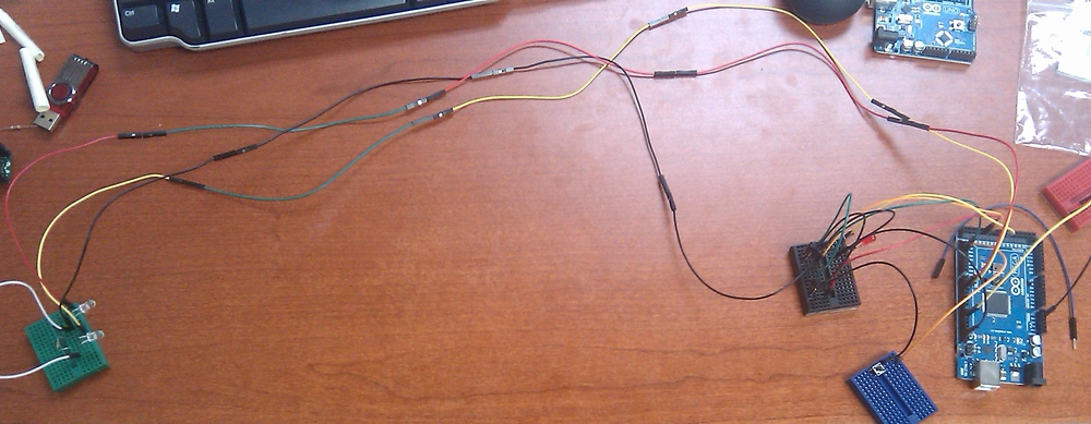
A couple things to note about this. I first had two levels working before I tried more. The way I set up the code, if you wanted to change it to utilize only two cases, you can make it so the ir_state variable only switches between 0 and 1, instead of 0 to 7, by changing the line if (ir_state > 7) to if (ir_state > 1). Here is a photo of the circuit with just two levels right next to each other working on my desk:
After getting two levels working, I continued adding each case to properly setup everything for each level. Last but not least, I added a siren light as well as a buzzer that plays a few tones for a 'you lose' type of sound that is triggered when the currently selected IR receiver detects an object. For the buzzer, you need a PWM pin and can use the tone() function. For the siren, a digital pin is used to turn a MOSFET transistor on that allows current to flow to the siren light and make it flash.
Physical Construction
With coding out of the way, it was time to build! We first built a wooden door frame for which we could later use to mount all out electronics. This was done with two 4x4”s for the base, two for the sides, a 2x4” for the top, and of course, a power drill and some wood screws.
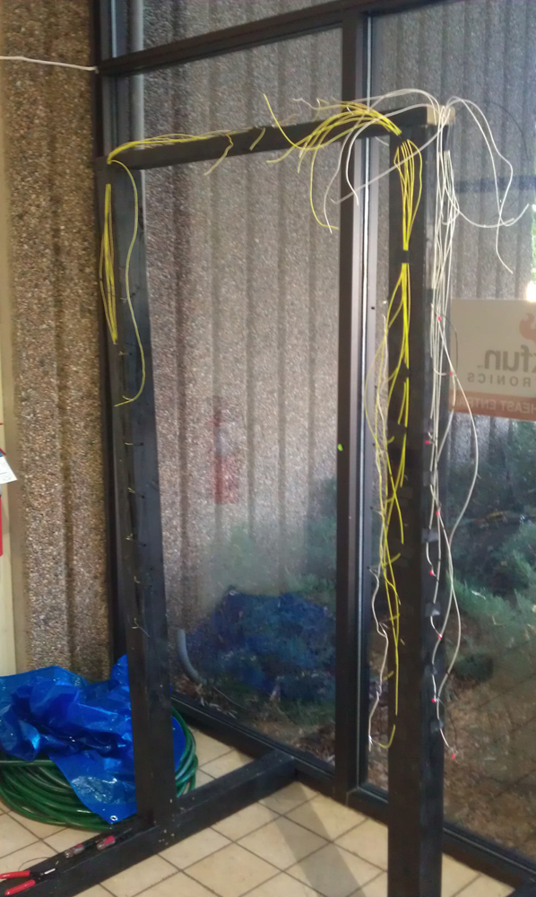
We first planned out the heights for each limbo level varying between 2.5 and 6 feet and then decided where to place our components. Along the left side, we mounted the IR LED's and measured and cut wires that would reach the top where the control board would be. On the right, we mounted the receiver's and the indicator LED's. We used a ton of hookup wire and this awesome butane powered soldering iron so we could solder wireless away from the desk. Just look at this wiring mess:
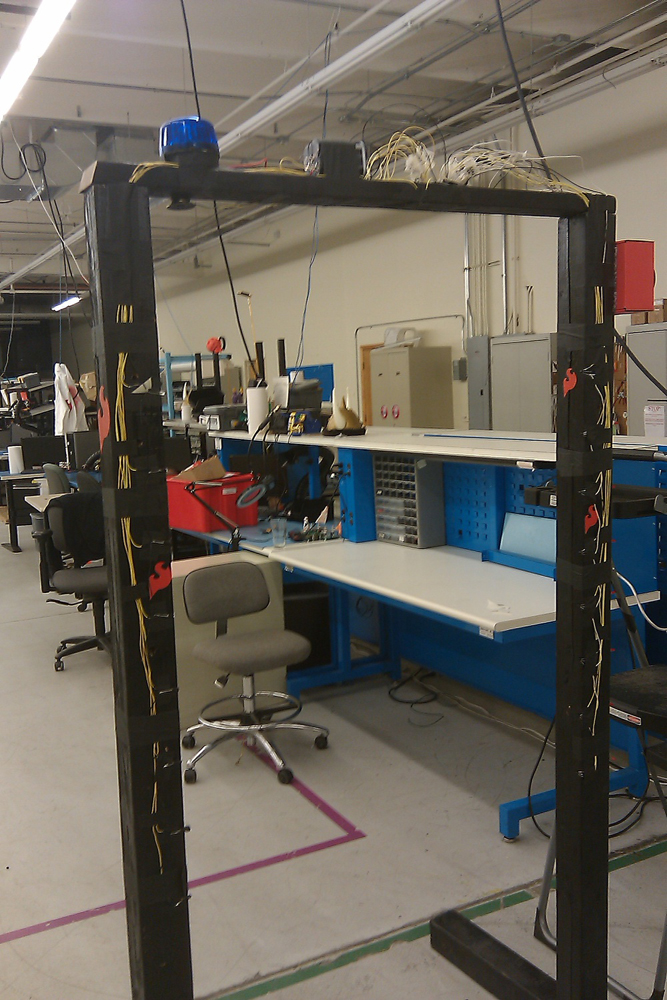
Once the components were wired and mounted, it was time to plug everything into the control board. We used a multimeter to verify we were connecting the right wire to the right pin on the Arduino, and labeled each as we were going in case we had to unplug the board later. We also mounted the siren, the massive button, and battery to the top of the frame. Here is a look of the top of the frame at this point:

Once everything was in place, we fired it up and surprise surprise, it didn't work the first time.... just like all electronic projects. After a couple hours of troubleshooting and trying different things, we determined we had a bad control board and so we swapped out the Arduino Mega 2560 for a new one. This time, it worked. Here is a picture of the final creation:
Not the prettiest thing ever, but here at SparkFun we like to show the guts that make it work.
Laser Limbo 2.0, who knows?
Overall, this was quite a fun project but there are many ways it can be improved. If I work on a project like this again, I'd love to make the level change mechanical, and maybe even use real lasers! Feel free to leave questions and comments.
great write up! Did you ever find out what caused a fried mega2560?
my suggestion for #2 is just like a force field. have a laser flood an area with its beam, so if it was foggy it would be a wall of light. now put a lot of receivers on the other side, so when the object passes threw it, it can detect the shadow of the laser and measure how low you went.
just imagine a penetrable force-field, that senses how large the object is going threw it.