
Setting up an EL display with the EL Escudo Dos
Good to Glow!
EL (electroluminescent) wire (and tape and panels) are neat products that emit light when high voltage is applied to them. The plastic material glows like neon, but runs cool, is thin and flexible, and is available in a number of colors. It's great for all kinds of artistic projects, from decorating your bedroom or bike, to parade floats, to joining the Tron Guy. Our CEO Nate made an interactive Heartbeat Straitjacket for Halloween, and lead engineer Chris turned our logo into this awesome flame:
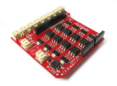
Sparkfun's EL Escudo Dos makes it easier than ever to create EL displays. This Arduino shield has connections for an EL inverter (a small module that generates high voltage AC), and provides eight EL output connectors that your Arduino sketch can turn on or off under software control. This allows you to easily create animated EL displays, signage, or whatever your imagination can come up with!
Before we go any further, here's a brief warning: EL WIRES RUN ON HIGH VOLTAGE. Don't worry, it's "only" 100V and very low current, so it's generally not dangerous. However, getting shocked is a bit unpleasant. If you're careful, there's no reason for this to happen. Unless you cut it (which you can, just insulate any exposed edges afterward), all EL wire / tape / panels safely seal the high voltage within a layer of plastic. But do keep in mind that like many of Sparkfun's products, the EL Escudo Dos is a bare board with exposed components and traces. To avoid shocks, always power down your entire circuit before plugging and unplugging connectors, and don't touch any exposed metal on the board while it's operating. For extra safety on public projects, we recommend enclosing it in a case or otherwise isolating it from curious fingers.
With that out of the way, let's get going!
Quickstart:
-
Solder stackable headers to the EL Escudo Dos.
-
Plug the EL Escudo Dos into the Arduino of your choice.
-
Attach an EL inverter to the "DC TO INVERTER" and "AC FROM INVERTER" connectors on the EL Escudo Dos. (You may need to configure the EL Escudo to ensure that the voltage coming from the "DC TO INVERTER" connector is appropriate for your inverter, see below.)
-
Attach your EL wire / tape / panels to the "A" through "H" output connectors.
-
Load the example sketch or your own code onto the Arduino.
- Glow!
Parts and tools needed:
In addition to an EL Escudo Dos, you'll need some or all of the following items:
- Soldering iron
- Solder
- Safety glasses
- One set of Arduino stackable headers (2 x 6-pin, 2 x 8-pin)
- A "full sized" Arduino (Pro, Uno, Leonardo, Mega, etc.)
- An EL inverter, such as Sparkfun's 3V or 12V models (see below for advice on choosing one)
- A power supply for the Arduino and inverter (12V supply recommended, see below)
- EL wire , tape, or panels with JST connectors, as required for your project
If you'll be modifying our 12V inverter for all-in-one operation (see below), you'll also need:
- A JST pigtail
- A small Phillips screwdriver, solder wick, and flush cutters
Soldering headers to the EL Escudo Dos
To plug your EL Escudo Dos into an Arduino, you'll first need to solder stackable headers to the board. (We don't preattach these to keep retail costs down, and because many users want to wire directly to the board.) If you've never soldered before, don't worry, it's easy, although you may want to practice on something else if this is your very first time soldering.
The six and eight-pin stackable headers go into the matching groups of six and eight holes on the board. (The correct holes are surrounded by white rectangles.) The black plastic socket side of the header goes on the component (top) side of the board, and and the pins stick out the bare (bottom) side of the board. An easy way to solder these headers to the board is to insert all four headers into the board, then flip the assembly upside down and place it on a flat surface. Then you can solder the joints from the bottom (now facing up) side of the board. Don't forget to wear your safety glasses!
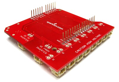
It's important for the headers to be soldered on straight so that they will easily plug into an Arduino, and other boards can plug into them. A good way to ensure this is to solder only one pin on each header, then check the alignment. If it's not straight, remelt the joint and quickly straighten up the header before the solder cools. Once the header is straight, finish soldering all the joints. Try not to get too much solder on the long pins that are sticking up, as these need to be clean in order to plug into the sockets on your Arduino. That wasn't so bad, was it?
Plug the EL Escudo into your Arduino, and let's keep going!
Choosing your inverter
To drive your EL wire, you'll need an EL inverter. An EL inverter takes in low-voltage DC, and boosts it to the high voltage AC (100V, 1000Hz) necessary to make EL wire glow.
SparkFun carries two inverters, a 3V version and a 12V version. The 3V version is great for battery-powered systems, but is best for small displays since it can only drive a few meters of EL wire. If you have 12V available, the 12V inverter is considerably stronger and is capable of driving dozens of feet of wire at high brightness.
 |
|
| 3V inverter (COM-10201) | 12V inverter (COM-10469) |
A note about brightness: The brightness you get will depend on the strength of your inverter and the total length of EL wire you're driving. The less EL wire you're driving, the brighter it will be. This is important to remember because the EL Escudo Dos has eight output channels. If you turn on only one channel at a time, the wire connected to that channel will be bright. But if you turn on multiple channels simultaneously, the brightness of all the EL strands will decrease, because the total length of EL wire you're driving has increased. If you use a strong inverter such as our 12V model, this generally isn't a problem, even for all eight channels being on simultaneously. However, for smaller inverters such as our 3V model, you may want to plan your display so that the wires are short and you're not driving too many channels simultaneously.
Connecting the 3V inverter
BEFORE CONNECTING ANY INVERTER OR EL WIRE TO THE EL ESCUDO DOS, ENSURE THAT EVERYTHING IS POWERED OFF!
Because of its low voltage requirements, Sparkfun's 3V inverter is ideal for small, battery-operated EL displays. The 3.3V supply built into many Arduinos is not strong enough to run this inverter, so the EL Escudo Dos has its own built-in voltage regulator. The regulator comes preset to 3.3V, which is ideal for this inverter, but it can be changed to other voltages for other inverters. See the schematic for details.
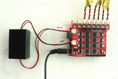
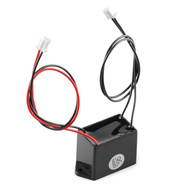
The 3V inverter has two JST connectors attached to it; a DC input (with red and black wires), and an AC output (with two black wires). To connect the inverter to the EL Escudo Dos, plug the JST connector with the red and black wires (the DC input) into the Escudo's "DC TO INVERTER" connector. Next, plug the JST connector with the two black wires (the AC output) into the Escudo's "AC FROM INVERTER" connector. That's it!
tl;dr: If you're powering your Arduino with 5V or above, you don't need to do anything more. If you're powering a 3.3V Arduino Pro with a Lipo battery, use your soldering iron to close the SJ1 solder jumper. Here's why:
The voltage regulator on the EL Escudo is connected to your Arduino's VIN pin, which is in turn connected to the raw power input to your Arduino. Depending on your Arduino and how you're powering it, this could be the power jack, the USB connector, or a battery connector.
The voltage regulator on the EL Escudo requires an input at least 1.5V above the output in order to operate. This means that the Arduino needs to be running on at least 4.8V for the regulator to be able to output 3.3V.
If you're running your inverter on less than that, such as a single-cell 3.7V Lipo battery, you can easily bypass the voltage regulator and directly connect VIN to the inverter. To do this, use your soldering iron to melt a blob of solder onto solder jumper SJ1, which is located just below the "C" in the "CAUTION HIGH VOLTAGE" label on the top side of the board. Note that when you close this jumper, you'll be sending whatever voltage is on the VIN pin directly to the "DC TO INVERTER" connector, so ensure that you're not powering your Arduino with more voltage than the inverter can handle. (The 3V inverter can take up to 4.2V, so it's safe to run on a Lipo battery, but once you make this modification, remember to not connect your Arduino to a higher-voltage supply without unplugging the inverter first!)
Connecting the 12V inverter
BEFORE CONNECTING ANY INVERTER OR EL WIRE TO THE EL ESCUDO DOS, ENSURE THAT EVERYTHING IS POWERED OFF!
If you have 12V available, or want to make the biggest, brightest display possible, Sparkfun's 12V inverter is a great choice.
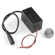
Off-the-shelf, the 12V inverter comes with a barrel plug connection for the DC input. This makes it easy to power directly from a 12V wall-wart. If you'd like to power it this way, connect the DC input to a 12V wall-wart, and connect the AC output JST connector to the Escudo's "AC FROM INVERTER" connector. That's it!
This setup works perfectly fine. But if you'd like to power both the inverter and the Arduino from a single 12V supply, you can easily modify the EL Escudo and inverter to do so. Here's how:
Step 1: getting 12V to the "DC TO INVERTER" connector
The EL Escudo Dos has a built-in voltage regulator that takes the raw voltage on the Arduino (VIN), and regulates it down for low-voltage inverters such as Sparkfun's 3V model. But since we can run both the inverter and the Arduino on 12V, we don't need that regulator any longer. We can bypass it by closing solder jumper SJ1, which is located just below the "C" in the "CAUTION HIGH VOLTAGE" label on the top side of the board. Use your soldering iron to place a blob of solder on that jumper, connecting both sides together. When you close this jumper, the VIN pin (12V) will be connected directly to the "DC TO INVERTER" connector, allowing you to power your inverter via the same 12V supply powering the Arduino.
Step 2: changing connectors on the inverter
The DC input on Sparkfun's 12V inverter has a connector that accepts a wall-wart plug. This is usually a great feature, but in this case, we'd rather have that input be a JST connector so we can hook it directly to the EL Escudo board. Never fear! We can easily hack one in.
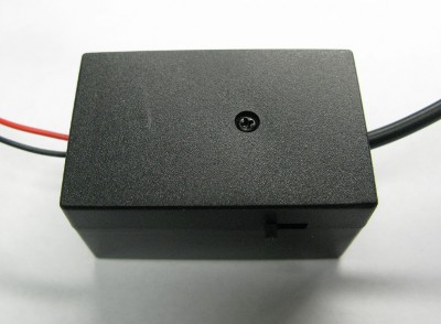
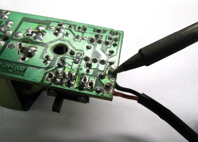
First, open up the inverter's case. It may look like there's no way to do so, but peel off the round sticker, and you'll find a Phillips screw below it (tricky!) Remove the screw, open the case, and take out the inverter's PCB.
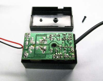
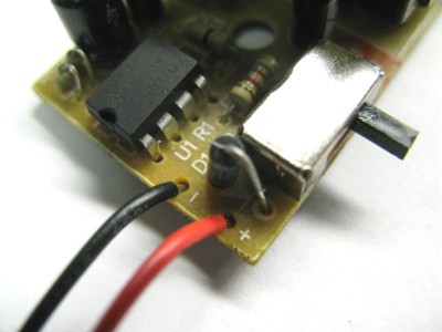
Next, remove the existing barrel-jack connector. Before doing so, make a note of where the red and black wires go on the PCB. (There should be "+" and "-" markings on the board, but you can't be too careful.) Heat up the solder on the bottom of the board, and pull out the wires one at a time. If the holes aren't clear when you're done, clean them out with solder wick, or melt the solder and immediately give the board a light rap on your workbench to clear out the holes. (You are wearing your safety glasses, aren't you?)
Now we'll solder in the new JST pigtail. Strip the wires a quarter-inch or so., insert one wire at a time into the proper location, and apply solder to the bottom of the board. When both wires are soldered, clip off any excess.
Before reassembling the case, it's a very good idea to mark which JST connector is the input, and which is the output, since they're now identical.
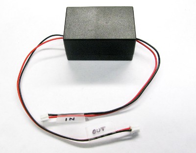
Put everything back together, plug the DC input you just made into the "DC TO INVERTER" connector, plug the AC output into the "AC FROM INVERTER" connector, and we're ready to fire things up!
Summary
| 3V inverter | 12V inverter | |
| 3.7V Lipo battery | close SJ1 | won't work |
| 5V supply | no changes needed | close SJ1, very dim |
| 9V supply | no changes needed | close SJ1, dim |
| 12V supply | no changes needed, but will run warm | close SJ1, bright! |
| > 13.5V supply | no changes needed, but will run warm | replace regulator resistors A and B for 12V output, see schematic and LM317 datasheet |
Attaching EL wire, tape, etc.
This is the fun part. Plug up to eight EL wires, tapes, panels, etc. into the output channels of the EL Escudo. These are the JST connectors labeled "A" through "H" along the edge of the board.
Now is a good time to mention that JST connectors can be very tight, especially when new. If you want to unplug something from a JST connector, don't pull on the wires. A good technique is to use a pair of wire cutters to grab the plug without squeezing, and pull it out of the socket:

Heat 'em up!
The moment has finally arrived! Connect your programming connector to the Arduino / EL Escudo stack, and power it up. Remember that once the inverter is powered up, portions of the circuit will have high voltage on them, so watch your fingers. (Handling the board by the Arduino itself is a good idea. You can also wait to attach the inverter until after you've programmed the Arduino, if desired. And if you're using the 12V inverter, it has a convenient on/off/blink switch you can use to keep it powered down until everything's ready.)
Once the Arduino is powered up, load the example code. Once it's running, both the status LED on the Arduino, and the status LED on the EL Escudo should be blinking. Turn on the inverter (if it isn't already), and hopefully you'll see your EL wire blinking away!
Troubleshooting
If nothing is happening, here are some things to check:
-
Are you running code that turns on that EL channel?
- (If you're running the demo code, the status light should be blinking rapidly.)
- If you're using the 12V inverter, is the inverter's built-in power switch on?
- Power everything off, and ensure the JST connectors are fully seated.
- Power up the board, and use a multimeter to check the DC voltage at the "DC TO INVERTER" connector (you can use the holes adjacent to the connector). Is the appropriate voltage for your inverter present?
- Power up the board, and (carefully) use a multimeter to check the AC output of the inverter, at the "AC FROM INVERTER" connector (you can use the holes adjacent to the connector). The inverter must be powered on for this test, and your multimeter must be set to VAC. Are you reading in the vicinity of 100VAC?
- If your EL wire is blinking, and you think it should be steady-on, and you're using the 12V inverter, check the position of the inverter's power switch. This inverter has a built-in blinking circuit which runs if the switch is in the middle position.
If you've checked all these things and you're still having problems, please feel free to contact our Technical Support department, who will be happy to help you out.
Programming
Programming the EL Escudo Dos is very easy. No libraries are needed; controlling the output channels is as simple as turning a LED on or off. In fact, that's exactly what you're doing - inside each of the eight optotriacs on the board is an LED that is internally coupled to a light sensor on the high-voltage side. By using light to bridge the gap between the AC and DC sides of the circuit, there is complete electrical isolation, which makes the board safe and reliable.
The eight EL channels, labeled "A" through "H" on the board, are linked to digital I/O pins 2 through 9. Before using a channel, make that pin an output using the command:
pinMode(pin,OUTPUT);
To make a channel turn on, make that pin HIGH with:
digitalWrite(pin,HIGH);
To make a channel turn off, make that pin low with:
digitalWrite(pin,LOW);
It's that easy! See the example code for a basic framework to build on.
Can I dim the EL wire?
The quick answer is not really. You may be able to achieve a few dimming levels by using the analogWrite() command, but because this board uses zero-crossing triacs and there's no synchronization between the AC waveform and your Arduino's PWM, dimming isn't terribly effective. Some analog levels will produce stable dimming zones, others will produce flickering. You can't hurt the board by doing this, so feel free to experiment; you will probably find a few levels that work well, and maybe flickering is exactly the effect you're looking for. Remember that not all pins on an Arduino support PWM, so you'll be limited to "dimming" channels B, D, E, and H.
Have fun!
If you have any questions, problems or tips you'd like to share, feel free to post them in the comments below or let us know. And if you build an awesome project, we'd love to hear about it (and maybe feature it on our front page!)
Have fun with your EL Escudo Dos!
-Your friends at Sparkfun.
Is it possible and/or has anyone tried stacking 2 Escudo boards on a single UNO?
Hello, I have my arduino and el escudo dos combo, with the 12v inverter modified and connected and everything runs smoothly. My question is, can I switch on / off my el wires through a command from a makey makey board? It is a unclear to me how to connect the makey makey to this setup. Thanks a lot
how do you program a chasing EL wire to get the movement effect ?
I have a problem with my dos. I am not using as a shield but just wiring the pins 5,6,7 to my bare conductive board and hooking it up to ground and a 12 power supply. The idea is when you touch one of the 3 of three touch pads on the bare board linked to pins 5, 6 or 7 the corresponding elwire strip comes on. Everything is working as it should but I can't get all 3 pieces of wire to turn off on those pins. They will turn on in series or together and are really responsive otherwise. It always wants to leave one on no mater what. I verified with my multimeter none of the arduino pins are sending voltage when this happens which means this is definitely happening on the el escudo. With regular LEDs, it's perfect so I do know the code is correct. Thoughts? Suggestion? Should I connect something else? An interrupt of some kind to a pin? I must be losing something not using it as a shield. Ideas?
First guess is there's something weird going on with your power supply system. Are you powering the shield and the inverter from the same 12V? Do you have a common ground between your bare conductive board and the Escudo? There also is the possibility that it could be an issue with the tape/wire you are using. Try switching the order that the wires are connected on the board and see if the issue follows a particular wire or if it stays on a certain pin on the Escudo. That will help narrow down where to check for issues.
Ok so I linked the inverter dc wires to the batt terminals, successfully uploaded the example code and soldered my own (lets call them positive) leads to each pinout with one common (negative) from pin 'A' linked in series to all the EL panels. My goal is to make a (one on at a time) chaser array but what I get is all the panels blinking on and off in unison. Does each panel require two independent leads. or did I muck something else up?
If you're using Sparkfun's 12V inverter, make sure that the switch is in the fully-on position. There's a middle position that blinks the output.
its a radioshack one that i bypassed so it only stays on solid. Using the latest board.
PS im using the latest mode sequencer and not escudo
can anyone tell me what board i need to set my arduino software to in order to upload
If you are using the Escudo Dos, you will set the Arduino software to whatever Arduino board you are using in conjunction with the Escudo shield.
Hi, I would like to use this sequencer with a Bare conductive touch board. It essentially works like an arduino but the board setup means I won't be able to plug the shield directly to this. Could you tell me which pins from the El Escudo need to be connected to the arduino board in order for for me to be able to program it? I will then just solder directly to the board. Thank you!
The EL Escudo uses Arduino pins D2 through D9 to control the eight output channels, and wants power on VIN and GND. If you don't need all eight channels you can just connect the control lines you do need.
Actually, I just tried the sequencer with 20ft of wire, and if I turn on the EL wire for more than 1-2 seconds, then I can't use
digitalWrite(pinMode, LOW) to turn it off anymore. At the moment, I am making a default LOW for a couple of seconds after any HIGH just to make sure it doesn't stay on for too long. Is there a maximum length of EL wire that can be controlled by the sequencer? Thx
Great thanks! I just got my sequencer and I've tested it with the teensy 2.0. Works well.
Hello, i have a question, i would like to make a el suit. I have a EL Wire lenght of 5 meters. Which inverter must i use
the 3V inverter should do..
Hello. I have the El Escudo Dos set up as mentioned above. It's connected with the pins to an Arduino Uno board. I have the 3 Volt inverter, and I have my laptop connected wtih USB to the Arduino to load the program.
I'm having issues loading the program though. It gives an error saying "Board at COM4 is not available" even though the IDE on the lower right portion says the Arduino Uno is at COM4.
So I have the following questions: 1) which version of the Arduino IDE was used in this tutorial? I currently have Arduino 1.5.5. 2) which board is selected under Tools->Boards? I've selected just Arduino Uno. 3) which programmer option was selected? (ie AVR ISP, AVRISP mkII, USBtinyISP, USBasp, Parallel Programmer, Arduino as ISP?) 4) is there any additional config files needed to make the Arduino Uno work with the El Escudo Dos, or El Sequencer? if so, how do you load it into the IDE?
Sorry for so many questions but I'm really trying to learn this, thanks.
Hey im having trouble turning on the status lights from the example code. I followed all the instructions and tested all the troubleshooting methods. Is there anything you suggest i test? This occurs on all 4 of my shields.
The above example code doesn't blink the status LEDs on both the shield and the Arduino? Does it blink either of them? Are you sure that this or any code, such as the basic "blink" sketch, is uploading to the Arduino properly? If you continue to have problems, contact our Tech Support Department who will be happy to help you.
Only the status light for the Arduino blinks from the example code. Also I rewritten the code so that the both status lights would be on but I still get only the Arduino to response. I have tested this on all my 4 shields and 4 Arduino Unos.
That's very strange, possibly bad stacking connectors between the Arduino and the shield? Sorry for the problems you're experiencing, I recommend contacting Tech Support, they'll be able to get you up and running.
Would there be a difference because I was using the breakaway headers -straight? Should I being using different headers? I will also contact Tech support.
LED instead of el wire?, or some other board?
Some other board. This board is exclusively for EL wire.
I recommend that board?
It depends on what you want to do, but most Arduinos can control about 18 LEDs directly and many more if you are using addressable LEDs.
I am trying to use the the El Escudo Dos with the capacitive touch sensor bob, and I have hit a snag: Is there any way for me to use digital pin 2 as an interrupt pin? I am afraid I'll fry whatever I plug into pin 2.
One idea is to cut the male stackable header on pin D2, in use a 90 degree pin to my bob.
Any suggestions appreciated. Also, if I understand correctly, if I short SJ1, the EL wire will run brighter? Thank you for your help. John
Hi, i just bought this one and connected with the arduino uno, soldered, connected with 12v inverter (soldered JS1) and its working with a 12v input through the ard. board I got a couple of questions..
thanks in advance
Hi, Great tutorial, thanks! I'm brand new to this and aim to build a wearable project. Is it possible to control the on/off illumination of a single EL Panel based on input from either a sound sensor (such as the Breakout Board for the Electret Microphone) or a distance sensor (like the Maxbotix Ultrasonic Range Finder)? For example, once the sound reaches a certain level, the EL panel turns on. I have a sketch that turns on a single LED based on the microphone's amplified input...wondering if it's compatible with the setup described here? Thanks in advance!
Hi there! If you have a sketch that turns on an LED when you want it to, then you can definitely get the EL Escudo or EL Sequencer to do what you want. The Arduino-side circuitry is based on LEDs turning on and off, so you should be all set. Have fun and please let us know if you have any questions or problems.
Hi Mike. Thanks for this tutorial.
Fairly new to this..
I have a particular scenario that's slightly different and I'm not sure how to proceed. Hope you can help.
I am working on a project that includes a Lilypad Simple (5v max), El Escudos Dos (12v fine) and a the EL 12v inverter to drive 3 EL panels 10x10cm (12v should be ok as only 2 would be on for a max of 8 seconds).
I have with me a couple of lipoly batteries a 3.7v and a 11.1v. What do you recommend on this setup? Ideally I would like to run all on the 11.1v lipoly but that would be the end of the Lilypad. Can I use the 3.7v to power the lilypad and the 11.1v directly to the inverter? Would this two battery setup still pass-through 12v to the inverter?
Thanks Juan
Update: Using the lilypad as this is a wearable project. Thanks.
Hi Juan, a two-battery setup is probably the simplest way to do this. Run the Lilypad off a 3.7V battery, and run your 11.1V battery into the VIN pin on the EL Escudo. Use your soldering iron to put a blob of solder on SJ1; this will send 11.1V to your 12V inverter. Now you just need to connect three of the LilyPad's outputs, to the inputs on the EL Escudo (you can use the row of eight holes near the status LED marked A through H). You should also connect a ground line between the LilyPad and the EL Escudo. Everything should work fine.
Two things I'll mention: when the inverter is on, portions of the EL Escudo will have exposed high voltage, so be careful not to locate it where you or someone else might touch it or brush against it (it's not dangerous, but it is unpleasant).
Also, since the EL Escudo wasn't really designed for fabric projects, instead of going through the trouble of connecting it to a LilyPad, you might consider just plugging a standard Arduino (such as a 5V Pro) into the EL Escudo. You could use one battery (your 11.1V) to power both the Arduino and the inverter. It will be a little bulkier, but because they just plug into each other it would be quite a bit easier to set up.
I hope this helps, good luck with your project!
Hi Mike,
This is excellent. Will def protect the circuitry with a 3D printed enclosure and layers of fabric.
I think I will try both options you suggested. The lilypad-El Escudo was my setup for the raw prototype. The project should evolve to include a GPS and a couple of sensors to trigger the EL panels.
I had not thought about using a 5V Pro but instead replacing the lily for a 5V Pro Mini when the prototype is fully working but I will be getting a 5V Pro as it will be indeed less hassle down the road and footprint is great. I am also considering building my own 4 port El-Escudo PCB so I can reduce the footprint and weight (any ideas if there is a 11.1v-happy commercial version I can use?). The ultimate goal is to stick to just one 11.1v battery setup for the whole project one that I can I can recharge via USB.
Will keep you posted on the progress.
My solution to the tight fitting JST connectors is to trim a bit of the height off of the locking pins, with a modelling knife, before the first use. This method maintains the locking function while reducing the release force below the breaking force of the wires.
I'm trying to run 7 pieces of 1 meter EL Tape and one 10x10 cm panel using a battery. What's the highest capacity LiPo I can use if I want to connect it to a 12V inverter?
Follow up? : Is it possible to run an Uno, El Escudo w/ 7 meter long tapes, one 10x10 panel, a Lilipad w/ approx 60 LED's all off of one LiPo? and still be portable? Or is it best to use separate batteries for the EL, Arduino, and Lilipads? Any comments/guidance is much appreciated. Can't access forums now, but I will post there as well when not confined by the corp firewall.
I'm not quite sure what you mean by "capacity". The way we define it (amp-hours), you can pick any "capacity" you want, from a stack of AAAs to a car battery. They will all provide the same voltage, but they will last for different amounts of time.
The first thing you should probably pick is a voltage, and since you're using the 12V inverter, you can use anything that's in the vicinity of 12V (running the inverter directly), or higher (using the regulator built into the EL Escudo).
For example, you could run the 12V inverter off an 11.1V Lipo directly. That battery is 1500mAh, so it can provide 1500mA for one hour, or 500mA for three hours, or 100mA for 15 hours. If you're running 60 LEDs at 10mA each, that's 600mA right there, and the inverter + EL will probably take another 100mA, so you're looking at two hours runtime (worst case, this will increase dramatically if you don't have all 60 LEDs on at the same time). If you need more runtime, there are other 12V batteries out there with different amp-hours, up to and including car batteries if you want your project to run for 100 hours or more.
I hope this helps, good luck with your project!
Thanks Mike! I see the 12v EL inverter has a barrel connector and JST. Do I need to cut the barrel jack and connect a jst cable instead? Also, how do you recommend connecting the Lipo to the arduino and shield? Can I have one battery for both or do they need seperate ones? At this point, the plan is to run the El Escudo and Arduino independent of the lilipad circuit. Thanks again. And that definitely helps.
The above tutorial has instructions on how to replace the barrel jack on the 12V inverter with a JST pigtail. Once you do this, you can run the Arduino and EL Escudo on the same power supply (connected to the main Arduino board).
To power the Arduino from a battery, the easiest thing to do is probably splice a barrel jack onto your battery. For one of our Arduino Pros. you could do the same thing with a JST connector.
Glad this helps, please let us know if you have any other questions!
Lets say I am using a 3v micro, is the logic going to be compatible with the optoisolators?
Yes, we've tested it and it works well with both 3.3V and 5V Arduinos.
Awesome, thanks!
Is a 7.4V Li-Po Battery with the 12V Inverter gonna turn my EL wire bright or dim ?
It will be somewhat dim, but may be usable in a dark location. If you can switch to a 3-cell 11.1V LiPo battery, you'll have a much brighter output.
Thanks.
Can you adjust the input voltage to the 12V inverter to adjust brightness?
Thanks for the detailed post!
Or the output of the inverter? In both cases I'm just thinking some simple analog circuit.
Interesting idea! The output of these inverters is roughly proportional to the input, so you could accomplish this by changing the input voltage. You might be able to do this by replacing one of the regulator adjustment resistors on the EL Escudo with a digital pot. Let us know if you try this out.
I have figured it out and digital pots won't work on many applications, too limited. They cannot block the 200V, around 2.15mA for 3 meter from inverter. If we were to block it from the battery, the current that flows from the battery is too high (around 20mA permeter). Digital potentiometers are too low power.
The closest thing to use a digital potentiometer is: Each continuous EL wire segments cannot have more than 1 meter. An inverter is needed for every segment of EL wire.
I wasn't referring to using the digital pot on the input to the inverter; this board contains an LM317 adjustable voltage regulator that includes two voltage-setting resistors. You may be able to replace one or both of these with a digital pot, which would affect the output from the regulator.
I wonder if I could just have a capacitor parallel to the output from Arduino before the phototriac? There is also a resistor in there that makes it a low pass filter. So then I could dim EL wire all the way without flicker?
Triacs don't run well unsaturated; they like to be either full-on or full-off. If you look into AC dimming, you'll see they typically you'll synchronize with the AC waveform and turn on/off at a specific point into that waveform. This takes more circuitry than is available on the EL Escudo or Sequencer.
Oh, but then it can only adjust all EL wire brightness at once.
Thanks!
Great post! Very detailed.